Method for driving liquid crystal display device

a liquid crystal display and driving method technology, applied in semiconductor devices, instruments, computing, etc., can solve the problems of not having the quality of moving images equal, not providing sufficient effects, and increasing flicker, so as to improve image quality, reduce the amount of change, and widen the viewing angle

Inactive Publication Date: 2008-11-20
SEMICON ENERGY LAB CO LTD
View PDF32 Cites 154 Cited by
  • Summary
  • Abstract
  • Description
  • Claims
  • Application Information

AI Technical Summary

Benefits of technology

[0021]As described above, a variety of methods have been studied to solve the problem of motion blur in hold-type display devices. However, such methods do not provide sufficient effects and have not yet have quality of moving images equal to that of impulse-type display devices. Further, in the method in which display of a black image is made closer to pseudo impulse-type display, flickers are increased. When a black image is displayed, luminance of an image is decreased, and power consumption is increased to provide the same level of luminance as in the case where a black image is not inserted. In the method of increasing frame frequency, data processing is complicated, and a driver circuit for high-speed processing is needed, which causes problems such as increase in manufacturing cost, heat generation due to the data processing, and increase in power consumption.
[0022]In view of the foregoing problems, a main object of the invention is to provide a display device in which quality (image quality) of still images and moving images is improved and a driving method of the display device. In particular, objects are to provide a display device without the problem of motion blur and a driving method of the display device, to provide a display device without flickers and a driving method of the display device, to provide a display device with wider viewing angles and a driving method of the display device, to provide a display device with higher response speed and a driving method of the display device, to provide a display device with reduced power consumption and a driving method of the display device, to provide a display device with reduced manufacturing cost and a driving method of the display device, and the like.

Problems solved by technology

However, such methods do not provide sufficient effects and have not yet have quality of moving images equal to that of impulse-type display devices.
Further, in the method in which display of a black image is made closer to pseudo impulse-type display, flickers are increased.
When a black image is displayed, luminance of an image is decreased, and power consumption is increased to provide the same level of luminance as in the case where a black image is not inserted.
In the method of increasing frame frequency, data processing is complicated, and a driver circuit for high-speed processing is needed, which causes problems such as increase in manufacturing cost, heat generation due to the data processing, and increase in power consumption.

Method used


Image

  • Method for driving liquid crystal display device
  • Method for driving liquid crystal display device
  • Method for driving liquid crystal display device

Examples


embodiment mode 1

[0200]In this embodiment mode, an example of a method for improving quality of images displayed on a display device is described.

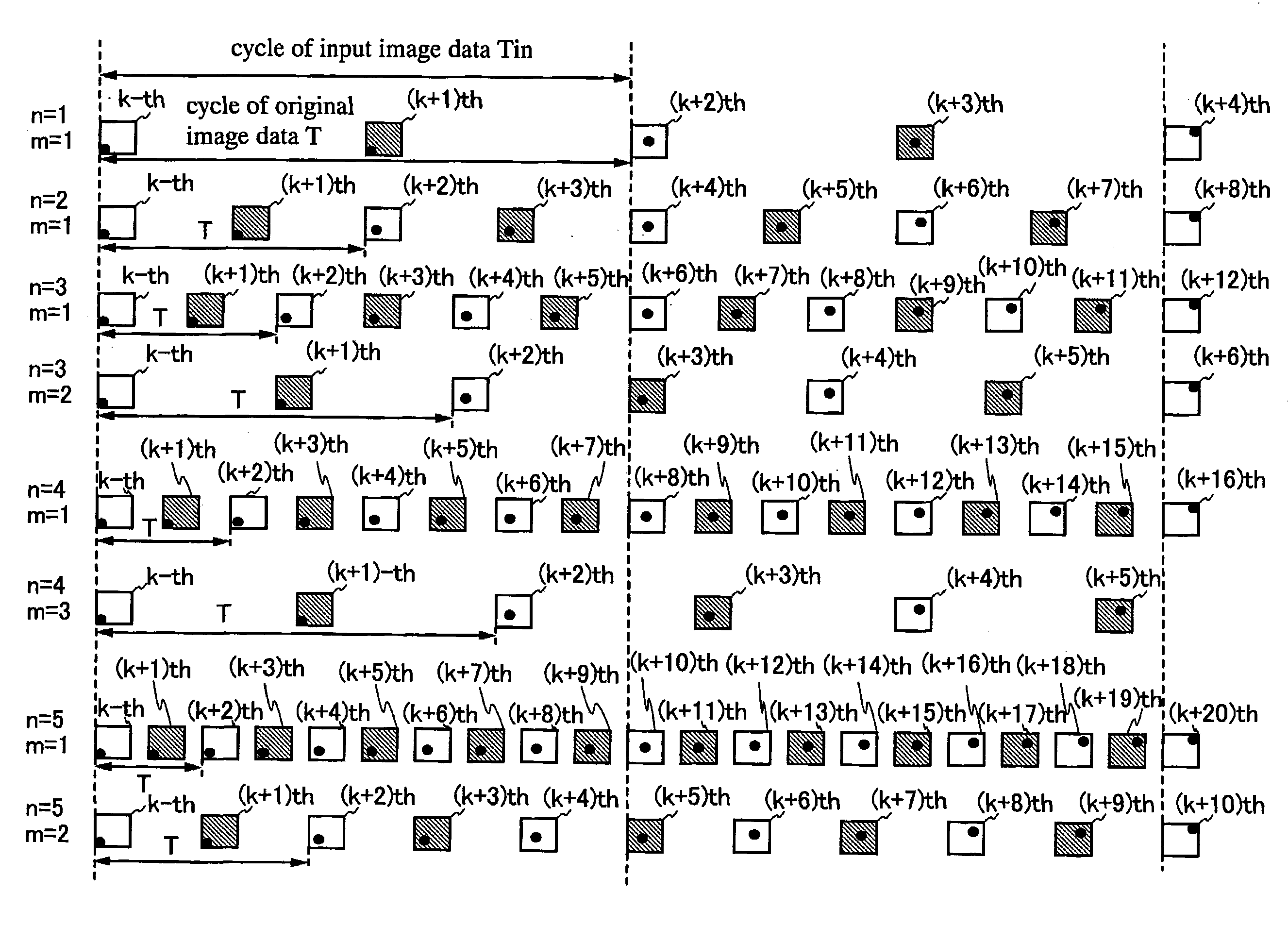
[0201]In this embodiment mode, a frame rate (the number of frames per second, unit: Hz, also referred to as input frame rate) of image data to be input does not necessarily correspond to a frame rate of display (also referred to as a display frame rate). When an input frame rate and a display frame rate are different from each other, the input frame rate can be converted by a circuit which converts a frame rate of image data (a frame rate conversion circuit) so that the input frame rate corresponds to the display frame rate. In such a manner, even when the input frame rate and the display frame rate are different from each other, display can be performed at a variety of display frame rates.

[0202]When the input frame rate is higher than the display frame rate, part of the image data to be input is discarded and the input frame rate is converted so that disp...

embodiment mode 2

[0516]In this embodiment mode, application examples of a method where image quality of a display device is improved, mainly change in driving method depending on circumstances are described. The circumstances here include contents of image data, environment inside and outside the device (e.g., temperature, humidity, barometric pressure, light, sound, electric field, the amount of radiation, altitude, acceleration, or movement speed), user settings, and software version.

[0517]A method in which movement of an image included in input image data is detected to form an intermediate image is described with reference to FIGS. 20A to 20E. FIGS. 20A to 20E schematically illustrate images displayed when the display frame rate is twice as high as the input frame rate. FIG. 20A schematically illustrates a method of detecting motion of the image with time represented by the horizontal axis. The period Tin represents a cycle of input image data. An image 2001 represents the p-th image. An image 2...

embodiment mode 3

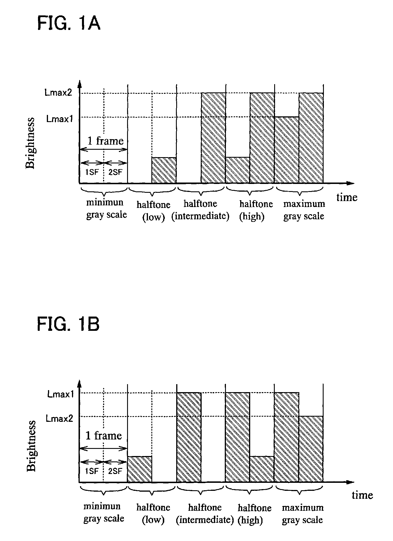
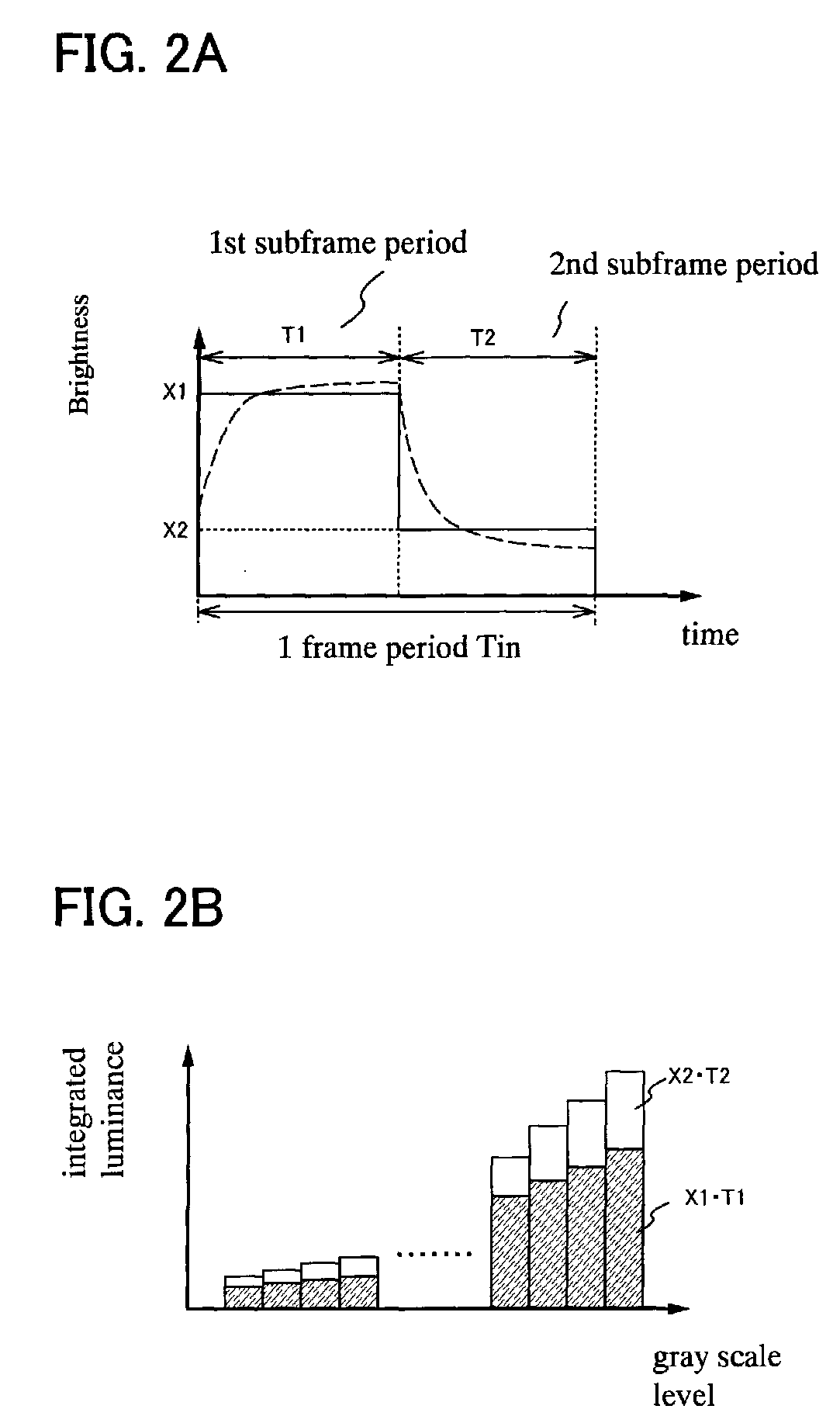
[0580]In this embodiment mode, a method for improving quality of moving images by dividing one frame into two or more subframes and using some of the two or more subframes mainly for display images (a bright image) and the others mainly for reducing afterimages of moving images (a dark image) is described.

[0581]Difference between a black image and a dark image is described. The black image is an image where all of the pixels for forming an image are in a non-lighting state or a non-transmitting state, and is just an inky black image. On the other hand, the dark image is an image formed when most of the pixels for forming an image emit light with relatively low luminance. In other words, the dark image is an image where the total amount of light emission of all the pixels for forming an image is smaller than that of a corresponding bright image. In accordance with this definition, the black image is used as the dark image in some cases.

[0582]Next, integrated luminance is described. I...


PUM


Abstract

In a period Tin, p-th input image data (p is a positive integer) and (p+1)th input image data are input to a liquid crystal display device. In a period T, i-th original image data (i is a positive integer) and (i+1)th original image data are generated based on the input image data. J number of sub-images (J is an integer equal to or more than 3) are generated based on the i-th original image data. In the period T, the J number of sub-images are sequentially displayed. At least one of the i-th original image data and the (i+1)th original image data is in an intermediate state between the p-th input image data and the (p+1)th input image data. Each of the sub-images exhibits one of first brightness and second brightness. At least one sub-image among the J number of sub-images is different from the other sub-images.

Description

BACKGROUND OF THE INVENTION[0001]1. Field of the Invention[0002]The present invention relates to devices and driving methods thereof. Specifically, the present invention relates to semiconductor devices and driving methods thereof. More specifically, the present invention relates to display devices and driving methods thereof, and particularly, methods for improving quality of moving images by a hold-type driving method.[0003]2. Description of the Related Art[0004]In recent years, there has been growing interests in thin display devices. As substitutes for CRT displays, liquid crystal displays, plasma displays, projection displays, and the like have been developed and becoming popular. Further, field emission displays, inorganic electroluminescence displays, organic electroluminescence displays, electronic paper, and the like have been developed as next-generation display devices.[0005]In a display portion provided in the above-described display device, pixels which are minimum unit...

Claims


Application Information

Patent Timeline
Patent Type & Authority Applications(United States)
IPC IPC(8): G09G5/00
CPCG02F1/1362H01L51/5012G09G3/2022G09G3/2025G09G3/2081G09G3/3233G09G3/3406G09G3/342G09G3/3648G09G3/3659G09G5/005G09G2300/02G09G2300/0408G09G2300/0443G09G2300/0465G09G2300/0819G09G2300/0842G09G2300/0876G09G2310/024G09G2310/0262G09G2310/061G09G2310/08G09G2320/0247G09G2320/0252G09G2320/0261G09G2320/0276G09G2320/028G09G2320/0633G09G2320/064G09G2320/106G09G2330/021G09G2340/0435G09G2340/16G09G2360/144G09G2360/16H01L27/1214H01L27/3244H01L29/42384H01L29/66772G09G3/2018H01L27/1266H10K59/12H10K50/11
Inventor YOSHIDA, YASUNORIKIMURA, HAJIME
Owner SEMICON ENERGY LAB CO LTD
Why Eureka
Try Eureka