Liquid Crystal Display Device and Driving Method Thereof

a liquid crystal display and driving method technology, applied in semiconductor devices, optics, instruments, etc., can solve the problems of not having the quality of moving images equal, flickering is increased, and the effect of not providing sufficient effects

Active Publication Date: 2008-11-20
SEMICON ENERGY LAB CO LTD
View PDF48 Cites 274 Cited by
  • Summary
  • Abstract
  • Description
  • Claims
  • Application Information

AI Technical Summary

Benefits of technology

[0077]A frame rate of input image data can be converted into a variety of display frame rates; thus, optimal display frame rate and driving method can be selected depending on circumstances, and a display device with a higher contrast ratio can be obtained. Accordingly, a display device with improved quality of still images and moving images and a driving method thereof can be obtained.
[0078]In addition, when a display frame rate is made larger than a frame rate of input image data or pseudo impulse driving is performed, for example, a display device without the problem of motion blur and a driving method thereof can be obtained. When a cycle of change in brightness is shortened or the amount of change is reduced, for example, a display device without flickers and a driving method thereof can be obtained. Further, particularly in a liquid crystal display device, when an optimal liquid crystal mode is selected, for example, a display device with wider viewing angles and a driving method thereof can be obtained. Moreover, particularly in a liquid crystal display device, when voltage whose level is larger than original voltage is temporarily applied to the device, for example, a display device with higher response speed and a driving method thereof can be obtained. By a variety of methods, for example, when brightness is suppressed or driving frequency is reduced, a display device with lower power consumption in addition to the above-described effects and a driving method thereof can be obtained. Further, by a variety of methods, for example, when a circuit for which high driving frequency is not necessary is used or a manufacturing process is simplified, a display device with lower manufacturing cost and a driving method thereof can be obtained.

Problems solved by technology

However, such methods do not provide sufficient effects and have not yet have quality of moving images equal to that of impulse-type display devices.
Further, in the method in which display of a black image is made closer to pseudo impulse-type display, flickers are increased.
When a black image is displayed, luminance of an image is decreased, and power consumption is increased to provide the same level of luminance as in the case where a black image is not inserted.
In the method of increasing frame frequency, data processing is complicated, and a driver circuit for high-speed processing is needed, which causes problems such as increase in manufacturing cost, heat generation due to the data processing, and increase in power consumption.
In addition, a variety of methods for improving a contrast ratio of a display device using a backlight have been studied; however, methods for improving quality of moving images as well as a contrast ratio are not considered.

Method used


Image

  • Liquid Crystal Display Device and Driving Method Thereof
  • Liquid Crystal Display Device and Driving Method Thereof
  • Liquid Crystal Display Device and Driving Method Thereof

Examples


embodiment mode 1

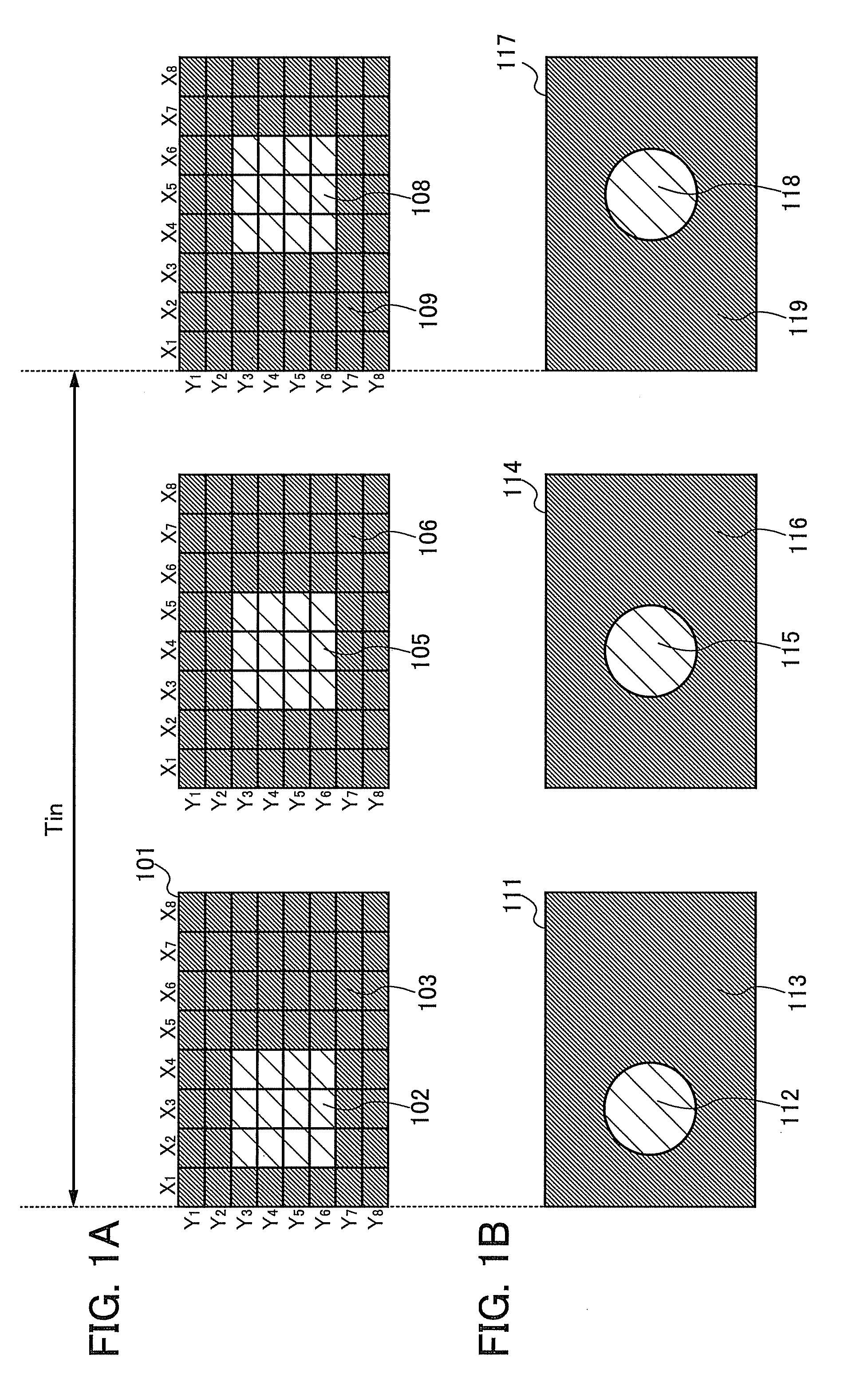
[0190]In this embodiment mode, an example of a method of improving quality of images displayed on a display device is described. Specifically, a method of improving quality of images displayed on a display device in which a backlight is used is described. More specifically, a method in which temporal change (movement of images) of image data to be input is detected and an image in an intermediate state between the images is employed as an interpolation image, and a method in which the area of a backlight is divided into a plurality of regions and brightness of each of the plurality of regions is controlled in accordance with image data to be displayed are described.

[0191]First, a backlight in this embodiment mode is described with reference to FIG. 1A. The backlight in this embodiment mode is a lighting device which illuminates a display panel from behind an image display region, and has a structure where a light-emitting region is divided into a plurality of unit regions and bright...

embodiment mode 2

[0252]In this embodiment mode, among methods of improving quality of images displayed on a display device, an example which is different from the method described in Embodiment Mode 1 is described. Specifically, a method of improving quality of images displayed on a display device by using a backlight is described. More specifically, a method of providing a period for displaying a blank image in addition to an image in accordance with image data input to the display device as images displayed on a display panel, and a method in which the area of a backlight is divided into a plurality of regions and brightness of each of the plurality of regions is controlled in accordance with image data to be displayed are described.

[0253]Here, a blank image is an image whose brightness is the same in the whole display region. Note that a blank image in this embodiment mode can be displayed by a display panel or a backlight. Examples of the blank image include a black image in which black is displ...

embodiment mode 3

[0279]In this embodiment mode, among methods of improving quality of images displayed on a display device, an example which is different from the methods described in Embodiment Modes 1 and 2 is described. Specifically, a method of improving quality of images displayed on a display device by using a backlight is described. More specifically, a method of providing a period for displaying a blank image in addition to an image in accordance with an image displayed on a display panel as images displayed on the backlight, and a method in which the area of a backlight is divided into a plurality of regions and brightness of each of the plurality of regions is controlled in accordance with image data to be displayed are described.

[0280]A backlight and a display panel in the method described in this embodiment mode can be the backlight and the display panel described in Embodiment Mode 1. Although detailed description is omitted, characteristics and advantages of use of such backlight and d...


PUM

PropertyMeasurementUnit
brightnessaaaaaaaaaa
overdrive voltageaaaaaaaaaa
voltageaaaaaaaaaa

Abstract

In a display device including a backlight and a display panel, the area of the backlight is divided into a plurality of unit regions; the display panel includes pixels which are larger in number than the unit regions; a frame rate of image data input to the device is converted to perform display while part of the unit regions in which black is displayed is in a non-light emission state; and the driving frequency of the backlight is converted in accordance with the display.

Description

BACKGROUND OF THE INVENTION[0001]1. Field of the Invention[0002]The present invention relates to devices and driving methods thereof. Specifically, the present invention relates to semiconductor devices and driving methods thereof. More specifically, the present invention relates to liquid crystal display devices and driving methods thereof, and particularly, liquid crystal display devices with improved contrast and driving methods thereof, and methods for improving quality of moving images.[0003]2. Description of the Related Art[0004]In recent years, there has been growing interests in thin display devices. As substitutes for CRT displays, liquid crystal displays, plasma displays, projection displays, and the like have been developed and becoming popular. Further, field emission displays, inorganic electroluminescence displays, organic electroluminescence displays, electronic paper, and the like have been developed as next-generation display devices.[0005]In a display portion provi...

Claims


Application Information

Patent Timeline
Patent Type & Authority Applications(United States)
IPC IPC(8): G02F1/13357G09G3/36
CPCG02F1/136277G09G3/3406G09G3/3426G09G2310/024G09G2320/0252G09G2320/0261G09G2320/0633G09G2320/0646G09G2320/103G09G2340/0435G09G2340/16G09G2360/16H01L27/12H01L27/1214H01L27/1266G02F2001/13613G02F1/13613G02F1/136209G02F1/136286G02F1/1368G02F1/13392G02F1/134309G02F1/1336
Inventor YOSHIDA, YASUNORI
Owner SEMICON ENERGY LAB CO LTD
Why Eureka
Try Eureka