Hand-held drive-in tool

a drive-in tool and hand-held technology, applied in the direction of paper/cardboard containers, container making machinery, dispensing apparatus, etc., can solve the problems of joule, low impact energy applied by the spring to the hammer body, and mechanical springs creating an increased portion of the drive-in tool rebound

Active Publication Date: 2008-12-04
HILTI AG
View PDF16 Cites 37 Cited by
  • Summary
  • Abstract
  • Description
  • Claims
  • Application Information

AI Technical Summary

Benefits of technology

[0017]This permits to combine in a simple manner the displacement energy of both drive springs and transmit the combined energy to the drive-in ram. The drive device can be formed, e.g., as a cable drive. The drive device ca...

Problems solved by technology

The drawback of a mechanical spring in comparison with a gas spring consists in that the mechanical spring creates an increased portion of the rebound of the drive-in tool during a setting process.
The drawback of the known drive-in tool consists in that the maximal impact energy applied by the spring to ...

Method used


Image

  • Hand-held drive-in tool
  • Hand-held drive-in tool
  • Hand-held drive-in tool

Examples


Embodiment Construction

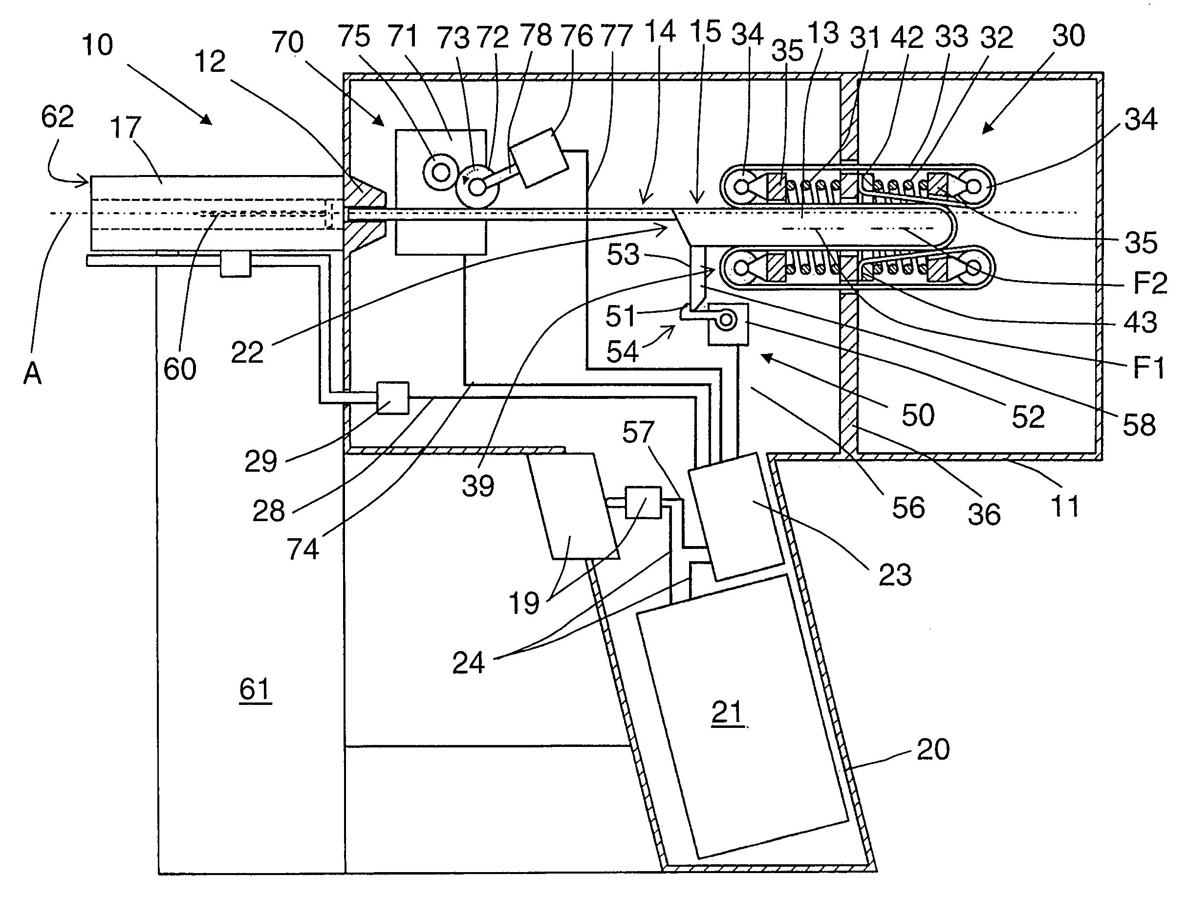
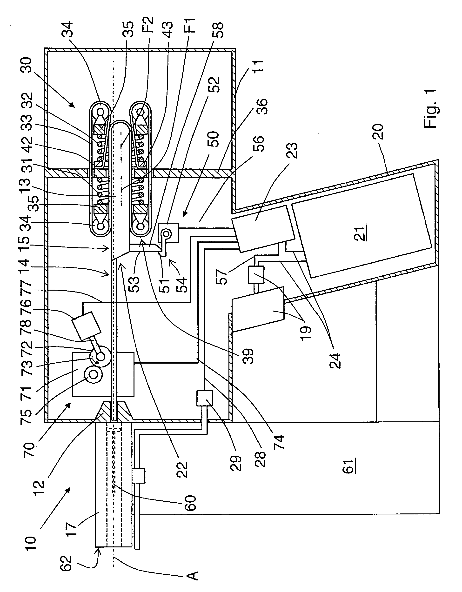
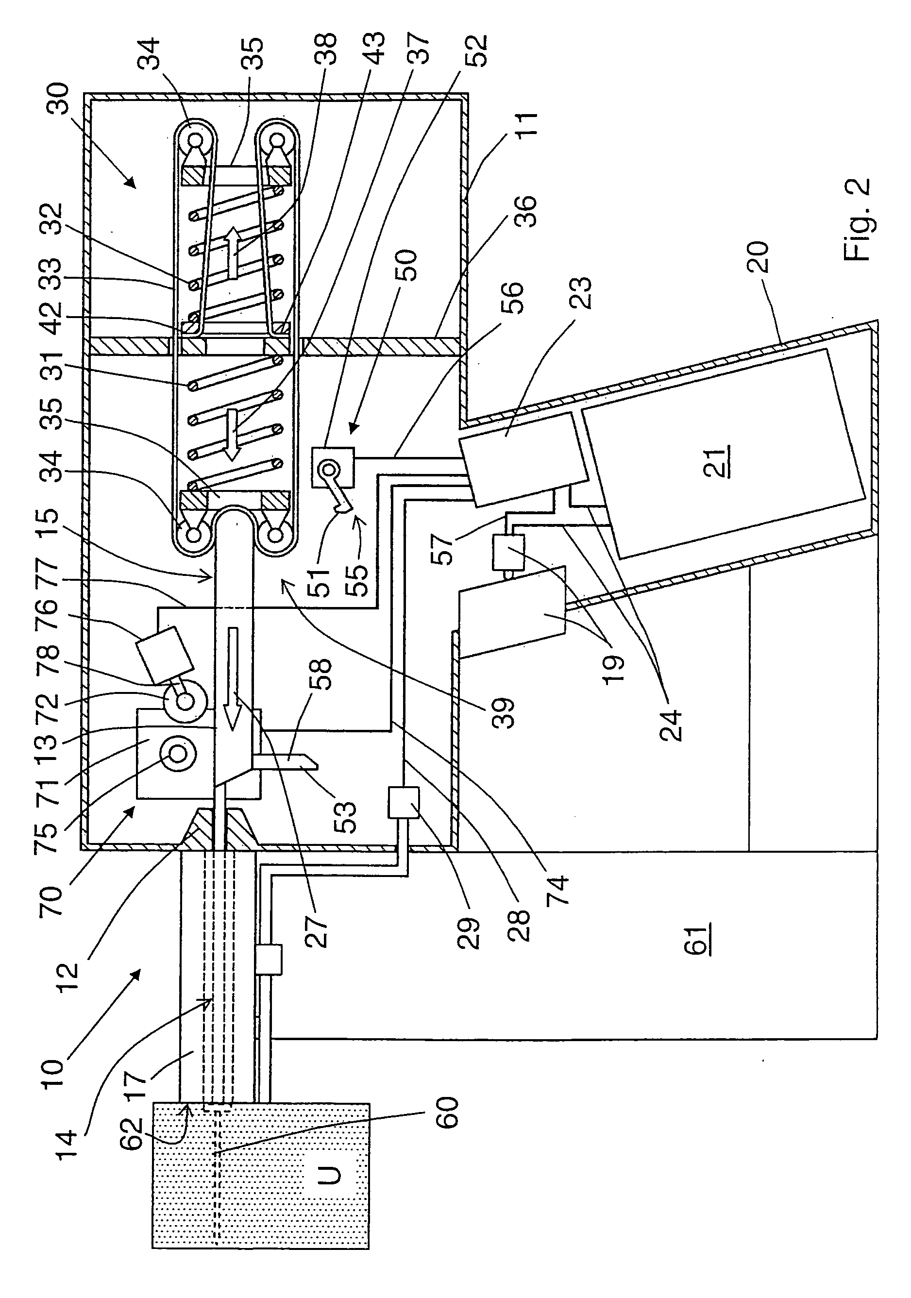
[0022]A hand-held drive-in tool 10 according to the present invention, which is shown in FIGS. 1-2, has a housing 11 and a drive unit 30 which is generally designated with a reference numeral 30 and in located in the housing 11. The drive unit 30 is designed for displacing a drive-in ram 13 in a guide 12. The drive-in ram 13 has a drive-in section 14 and a head section 15. A bolt guide 17 adjoins an end of the guide 12 extending in a drive-in direction 27. The bolt guide 17 is arranged coaxially with the guide 12. A magazine 61 for fastening elements 60, in which the fastening element 60 are stored, projects sidewise of the bolt guide 17.

[0023]The drive unit 30 includes a first drive spring 31 and a second drive spring 32. Both springs 31, 32 have substantially the same spring mass and are supported against a support element 36, which is formed integrally with the housing 11 or is fixedly secured therein, opposite each other. Both springs 31, 32 are formed as helical springs. Drive ...


PUM


Abstract

A hand-held drive-in tool for driving fastening elements in a workpiece and including a guide (12), a drive-in ram (13) displaceable in the guide (12) for driving a fastening element in, a drive-in unit (30) for driving the drive-in ram (13) and including at least one first drive spring (31) and at least one second drive spring (32) having respectively, opposite first and a second expansion directions (37, 38), and a tensioning device for preloading the drive-in ram (13) and the first drive spring (31).

Description

BACKGROUND OF THE INVENTION[0001]1. Field of the Invention[0002]The present invention relates to a hand-held drive-in tool for driving fastening elements in a workpiece, comprising a guide, a drive-in ram displaceable in the guide for driving a fastening element in, a drive-in unit for driving the drive-in ram and including at least one or first drive spring having a first expansion direction, and a tensioning device for preloading the drive-in ram and the at least one drive spring.[0003]2. Description of the Prior Art[0004]In the drive-in tools of the type discussed above, a mechanical drive spring, which is preloaded by a tensioning device, is used as a drive source. An advantage of this consists in that a mechanical drive spring is economical so that a drive-in tool with such drive spring can be economically produced. Further, an advantage of a mechanical drive spring in comparison with a gas spring consists in that preloading of a mechanical spring does not lead to a temperature...

Claims


Application Information

Patent Timeline
IPC IPC(8): B25C1/18
CPCB25C1/06B25C5/15
Inventor FIELITZ, HARALDODONI, WALTERSPASOV, ROBERT
Owner HILTI AG
Why Eureka
Try Eureka