Traffic lane management system

a management system and traffic lane technology, applied in the field of traffic lane management system, can solve the problems of insufficient resources to build additional physical road capacity, anemic growth in physical road capacity, and traffic congestion becoming a significant impediment to the quality of life in urban areas

Inactive Publication Date: 2008-12-04
ORIGIN TECH LTD
View PDF11 Cites 79 Cited by
  • Summary
  • Abstract
  • Description
  • Claims
  • Application Information

AI Technical Summary

Benefits of technology

[0022]In some embodiments, the control system imposes a fee upon the user if after the acceptance the vehicle fails to enter the traffic lane during the time slot.
[0023]In some embodiments, the control system deems the time slot rejected if the user foils within a predetermined time less than fifteen seconds after the offer to input on the user interface an acceptance of the time slot.

Problems solved by technology

Traffic congestion has become a significant impediment to the quality of life in urban areas.
The United States Department of Transportation (USDOT) has indicated that there are insufficient resources to build additional physical road capacity at a rote to keep up with demand.
High costs to add physical road capacity and long timelines for deployment have led to anemic growth in physical road capacity in some urban areas.
However, there is often a significant amount of excess capacity that goes unutilized even during rush hour conditions.
This has led to greater utilization of HOV lanes; however, in congested areas it has adversely impacted carpoolers.
However, the “tolling” aspect of HOT lane tolling is often politically unpopular and has proven a serious drawback.
Others object to the fact that a certain segment of the population cannot afford the tolls.
Even where the political obstacles to installation of HOT lane tolling systems hove been overcome and such systems have been deployed, resistance to the tolls has sometimes led to underutilization of such systems and resulted in a failure to achieve congestion management objectives.
As the flow rote approaches 2,500 vehicles per lane per hour, however, the “Unstable” region is entered and traffic conditions can dramatically deteriorate.

Method used


Image

  • Traffic lane management system
  • Traffic lane management system
  • Traffic lane management system

Examples


Embodiment Construction

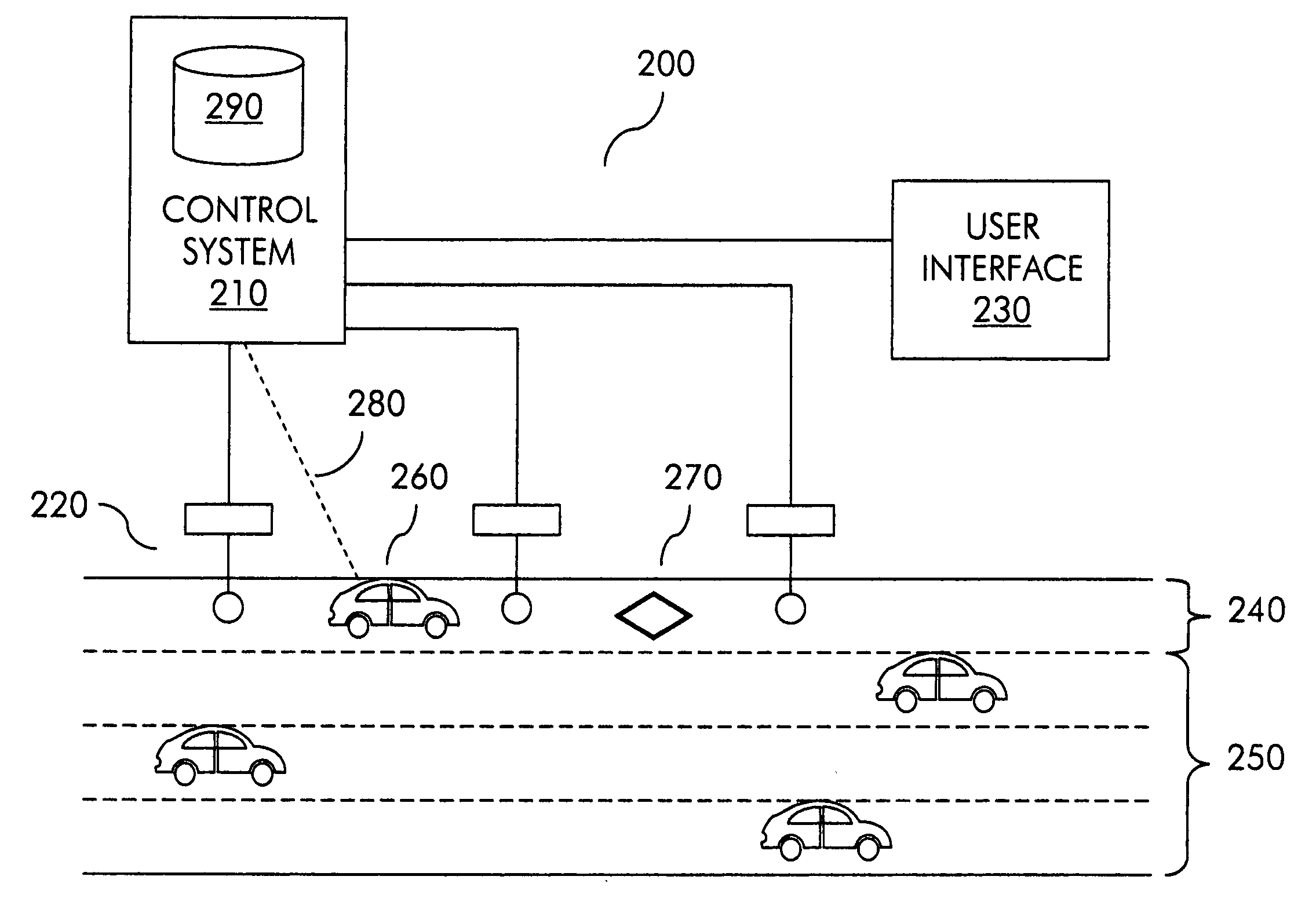
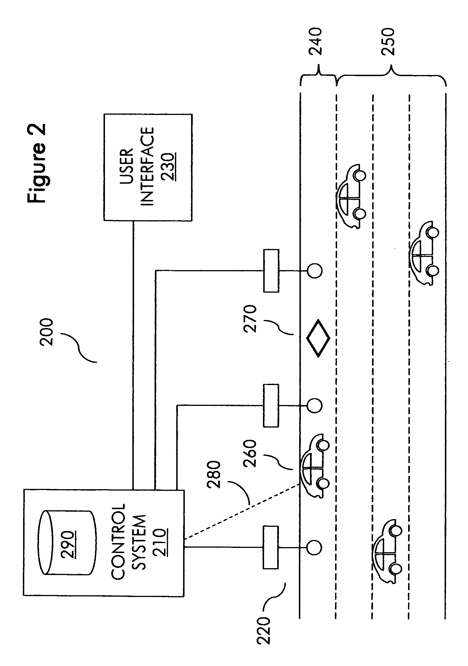
[0037]FIG. 2 shows a management system 200 for a traffic lane in some embodiments of the invention. Management system 200 manages a managed traffic lane 240 of a road having managed lane 240 as well as unmanaged traffic lanes 250. In other embodiments of the invention, a management system may manage multiple or all lanes of a given road. Unmanaged lanes 250 can be lawfully used by all vehicles at all times when unmanaged lanes 250 are in service. Managed lane 240 can be lawfully used only by vehicles that are presently authorized to use managed lane 240. Authorized times for at least some vehicles to use managed lane 240, hereinafter “regulated vehicles, are assigned by management system 200 based on a current prediction about future vehicle density in managed lane 240. Managed lane 240 has markings (e.g. 270) to help drivers of vehicles (e.g. 260) identify managed lane 240 as managed.

[0038]Management system 200 includes a control system 210, a detection system 220 and a user interf...


PUM


Abstract

A management system for a traffic lane achieves congestion management objectives by dynamically predicting future vehicle density in a traffic lane and assigning to a requesting user a time slot for entering the traffic lane selected independent of any user requested time and based at least in part on a current prediction about future vehicle density in the traffic lane. The current prediction is based at least in part on predicted trajectories of vehicles, which are determined in turn based at least in part on actual trajectories of vehicles.

Description

CROSS-REFERENCE TO RELATED APPLICATION(S)[0001]This application claims priority benefits under 35 U.S.C. 119(e) from U.S. provisional patent application Ser. No. 60 / 932,737, filed Jun. 1, 2007, entitled “VEHICLE SCHEDULING CONGESTION MANAGEMENT SYSTEM.”BACKGROUND OF THE INVENTION[0002]The present invention relates to a management system for a traffic lane, and more particularly to a management system for a traffic lane that achieves congestion management objectives by dynamically predicting future vehicle density in the traffic lane and assigning to a requesting user a time slot for entering the traffic lane selected independent of any user requested time and based at least in part on a current prediction about future vehicle density in the traffic lane.[0003]Traffic congestion has become a significant impediment to the quality of life in urban areas. Physical road capacity (lane-miles) of the nation's roadway system has grown slowly over the lost quarter century whereas vehicle mil...

Claims


Application Information

Patent Timeline
Patent Type & Authority Applications(United States)
IPC IPC(8): G08G1/00G06F3/048
CPCG08G1/0104G08G1/0112G08G1/0116G08G1/0129G08G1/0145G08G1/017G08G1/04G08G1/042
Inventor PETRISOR, GREGORY C.PERDUE, RYAN A.
Owner ORIGIN TECH LTD
Why Eureka
Try Eureka