Eureka AIR delivers breakthrough ideas for toughest innovation challenges, trusted by R&D personnel around the world.

Block splitter assembly and method of producing wall blocks

Active Publication Date: 2008-12-11
KEYSTONE RETAINING WALL SYST
View PDF31 Cites 46 Cited by
  • Summary
  • Abstract
  • Description
  • Claims
  • Application Information

AI Technical Summary

Benefits of technology

[0008]The invention provides a block splitter assembly that provides a more complex form to the block than the standard

Problems solved by technology

As the forces on the blades are increased, the workpiece splits (cracks) generally along the plane of alignment of the blades.

Method used


Image

  • Block splitter assembly and method of producing wall blocks
  • Block splitter assembly and method of producing wall blocks
  • Block splitter assembly and method of producing wall blocks

Examples


Embodiment Construction

[0036]The invention relates to the splitting of concrete wall block workpieces to create a more complex appearance to the faces of concrete retaining wall blocks that result from splitting the workpieces. Block splitter assemblies are described in U.S. Pat. Nos. 6,321,740 B1 and 6,874,494 B2, the contents of each of which are hereby incorporated by reference herein. The invention may be used with any variety of blocks molded or formed through any variety of processes.

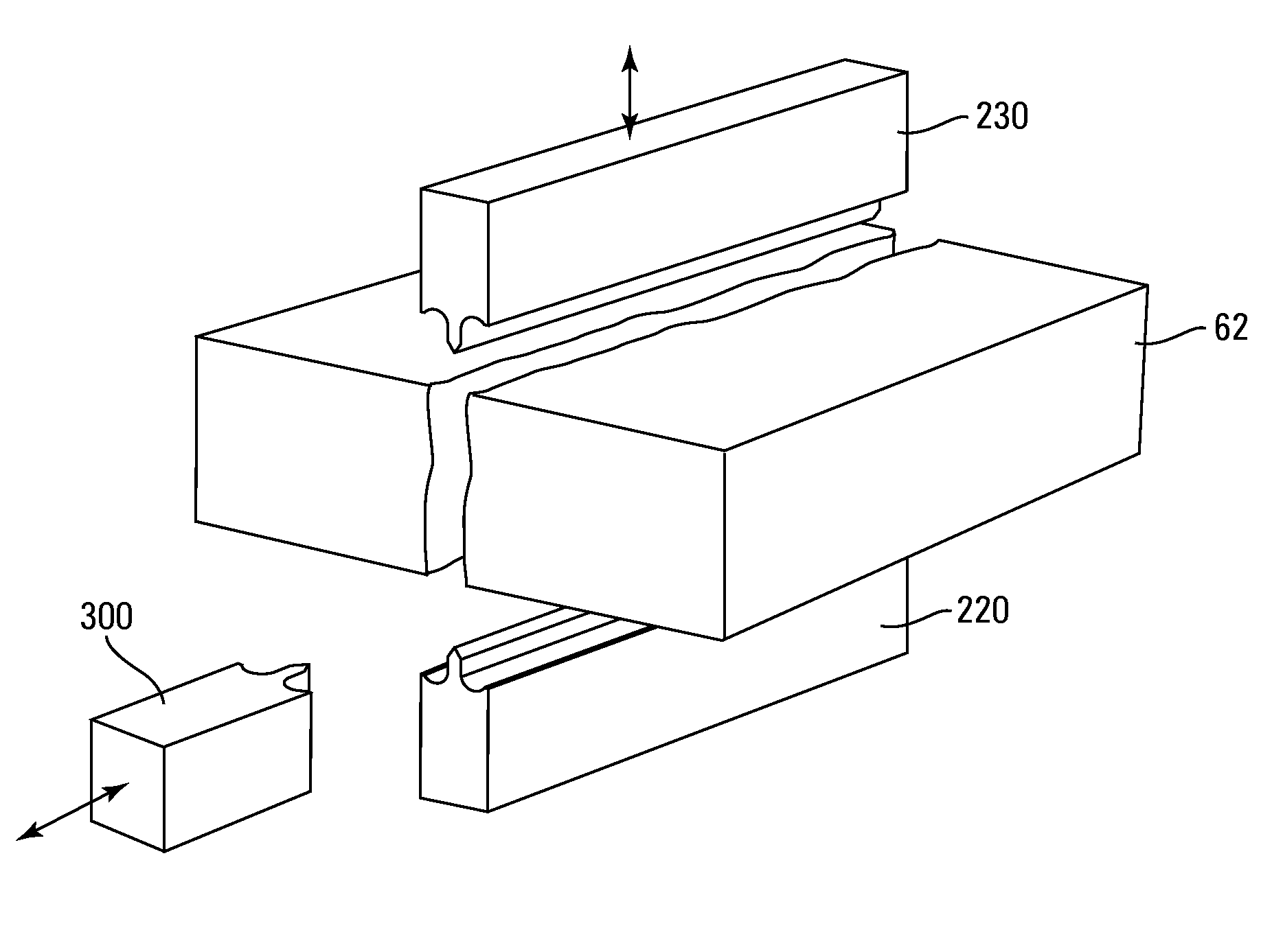
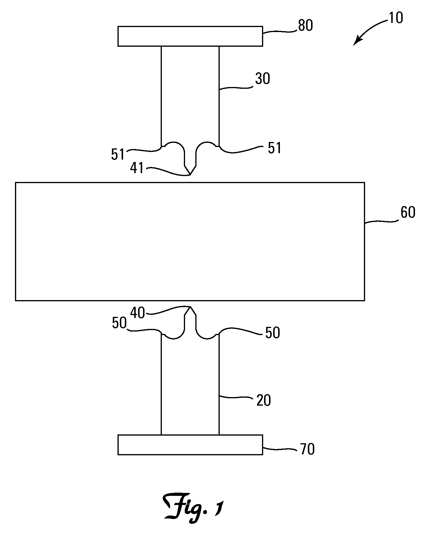
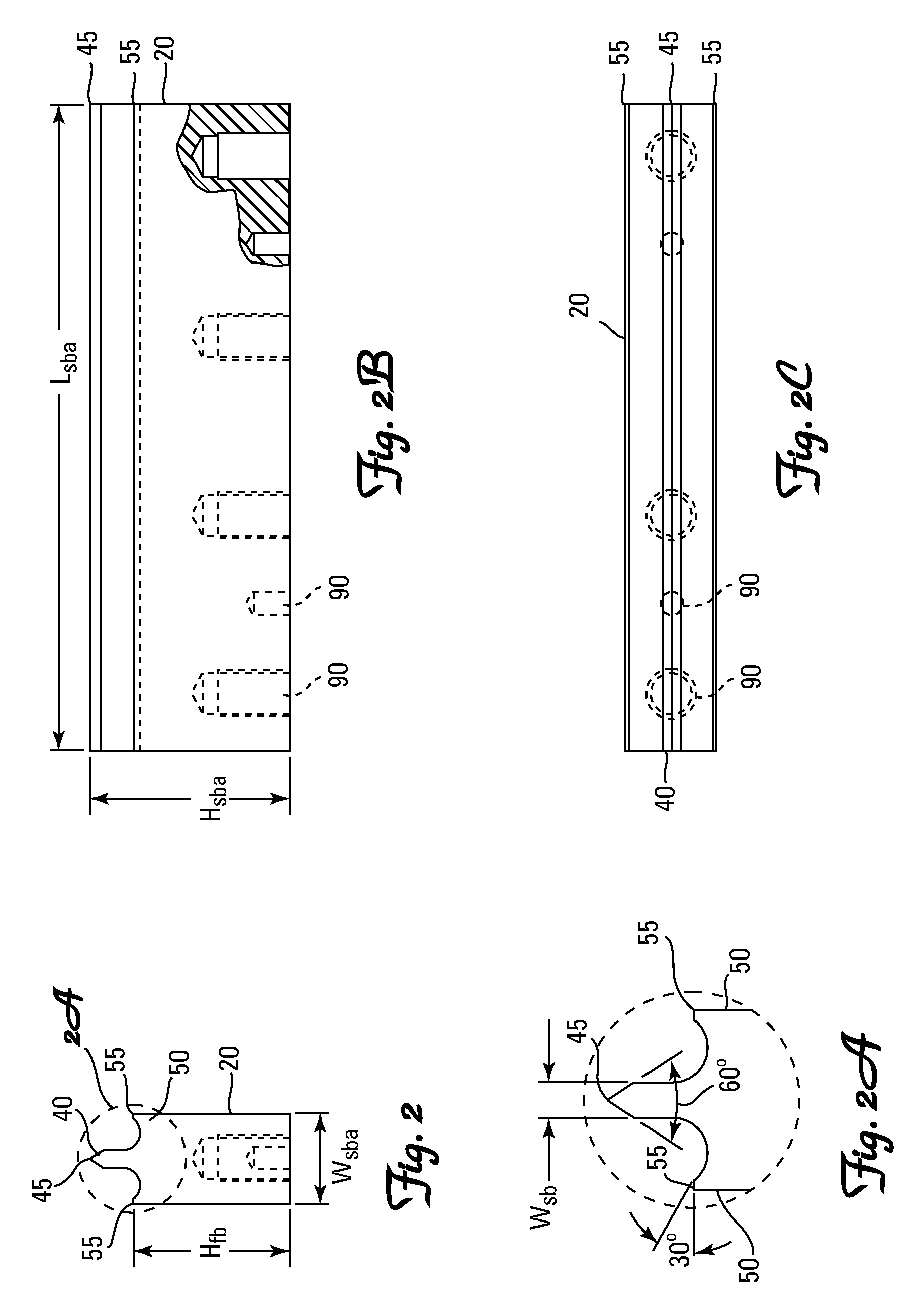
[0037]The invention provides a block splitter assembly comprising first lower and second upper opposed splitter blade assemblies. The first splitter blade assembly has a single first splitting blade and exactly two first forming blades. One first forming blade is disposed to the right of and one first forming blade is disposed to the left of the first splitting blade. The two first forming blades have forming edges. The first splitting blade has a splitting edge that is straight. The first splitting blade has a greater ...


PUM

PropertyMeasurementUnit
Lengthaaaaaaaaaa
Lengthaaaaaaaaaa
Lengthaaaaaaaaaa

Abstract

The invention provides a block splitter assembly comprising first lower and second upper opposed splitter blade assemblies. The splitter blade assemblies have a splitting blade and two or more first forming blades. One forming blade is disposed to the right of and one forming blade is disposed to the left of the first splitting blade. The forming blades have forming edges. The splitting blade has a splitting edge that is straight, and the splitting blade has a greater maximum vertical dimension than the maximum vertical dimension of the forming blades. The splitting edge of the first splitting blade is opposed to the splitting edge of the second splitting blade.

Description

[0001]This application claims the benefit of U.S. Provisional Application No. 60 / 933,309, filed Jun. 6, 2007, entitled “Block Splitter Assembly and Method of Producing Wall Blocks”, the contents of which are hereby incorporated by reference herein.FIELD OF THE INVENTION[0002]The invention relates generally to the manufacture of concrete wall blocks. More specifically, it relates to equipment and processes for the creation of faces on concrete wall blocks, especially a block splitter.BACKGROUND OF THE INVENTION[0003]Retaining walls are used in various landscaping projects and are available in a wide variety of styles. Numerous methods and materials exist for the construction of retaining walls. Such methods include the use of natural stone, poured concrete, precast panels, masonry, and landscape timbers or railroad ties.[0004]A widely accepted method of construction of such walls is to dry stack concrete wall units, or blocks. These blocks are popular because they are mass produced a...

Claims


Application Information

Patent Timeline
IPC IPC(8): B28D1/32B28D1/26
CPCB28B17/0027B28D1/006B28D1/222B28D1/26
Inventor LACROIX, DAVID M.
Owner KEYSTONE RETAINING WALL SYST
Why Eureka
Eureka Blog
Learn More