Manufacturing method of casting, manufacturing device thereof, and casting

Active Publication Date: 2015-03-12
TOYOTA JIDOSHA KK +1
View PDF1 Cites 4 Cited by
  • Summary
  • Abstract
  • Description
  • Claims
  • Application Information

AI Technical Summary

Benefits of technology

The present invention provides a method and device for manufacturing castings with increased freedom of design and increased productivity. A simple method is used to increase the degree of freedom of castings, especially those with complex forms. This allows for more efficient and effective casting production.

Problems solved by technology

However, with some upward continuous casting methods, there is a problem that the outer contour of a casting is defined by guide rollers, and castings that can be manufactured are limited to castings having simple forms, such as a tapered round bar.
Also, with some free casting methods, there is a problem that an outlet of molten metal is restricted by a form or a partition member provided above the bath surface of a molten metal bath, and the degree of freedom of the form of a casting to be manufactured is low.

Method used


Image

  • Manufacturing method of casting, manufacturing device thereof, and casting
  • Manufacturing method of casting, manufacturing device thereof, and casting
  • Manufacturing method of casting, manufacturing device thereof, and casting

Examples


embodiment 1

of Casting and Manufacturing Device Thereof

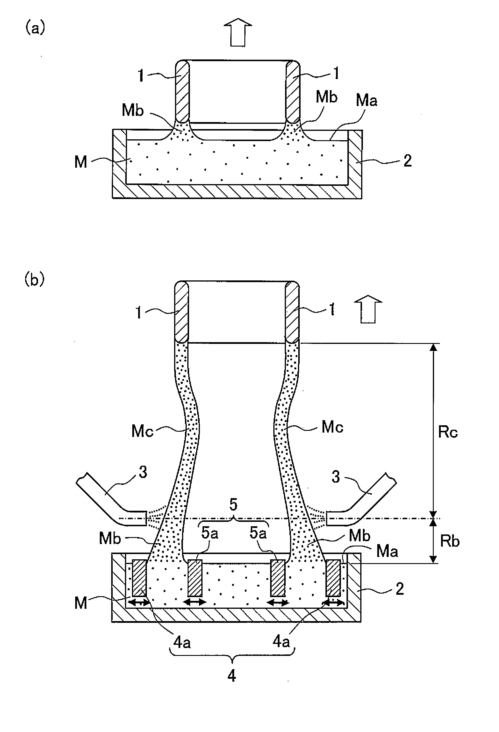
[0058]FIG. 4 is a perspective view showing an embodiment 1 of a manufacturing device of a casting of the present invention. Also, FIG. 5 is a view describing a state immediately after drawing out of molten metal from a molten metal bath using the manufacturing device shown in FIG. 4, and FIG. 5(a) is a vertical cross-sectional view thereof and FIG. 5(b) is an arrow view along line A1-A1 in FIG. 5(a). Also, FIG. 6 is a view describing a state where a part of molten metal drawn out from a molten metal bath using the manufacturing device shown in FIG. 4 is solidified, and FIG. 6(a) is a vertical cross-sectional view thereof and FIG. 6(b) is an arrow view along line B1-B1 in FIG. 6(a). Furthermore, FIG. 7 is a perspective view showing an embodiment 1 of a casting manufactured by the manufacturing device shown in FIG. 4.

[0059]A manufacturing device 10A shown in FIG. 4 includes a molten metal bath 2A for storing molten metal M, cooling means 3A f...

embodiment 2

of Casting and Manufacturing Device Thereof

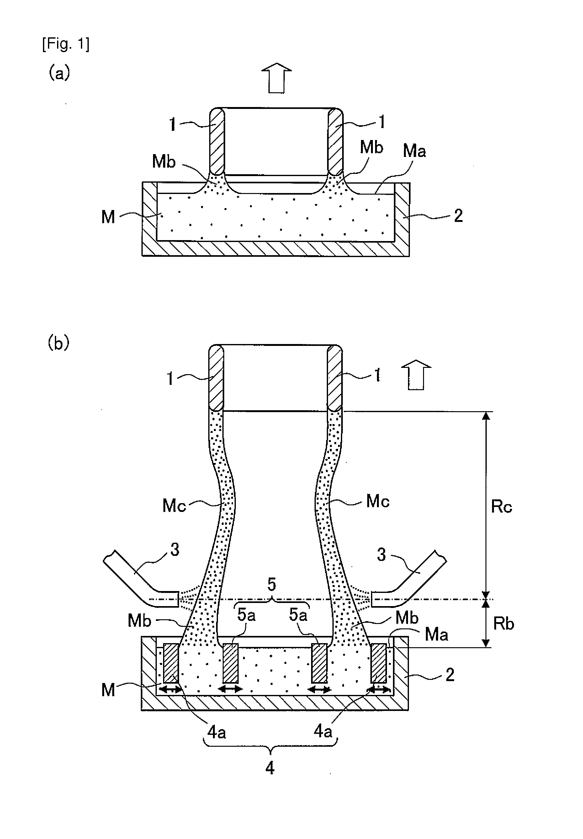
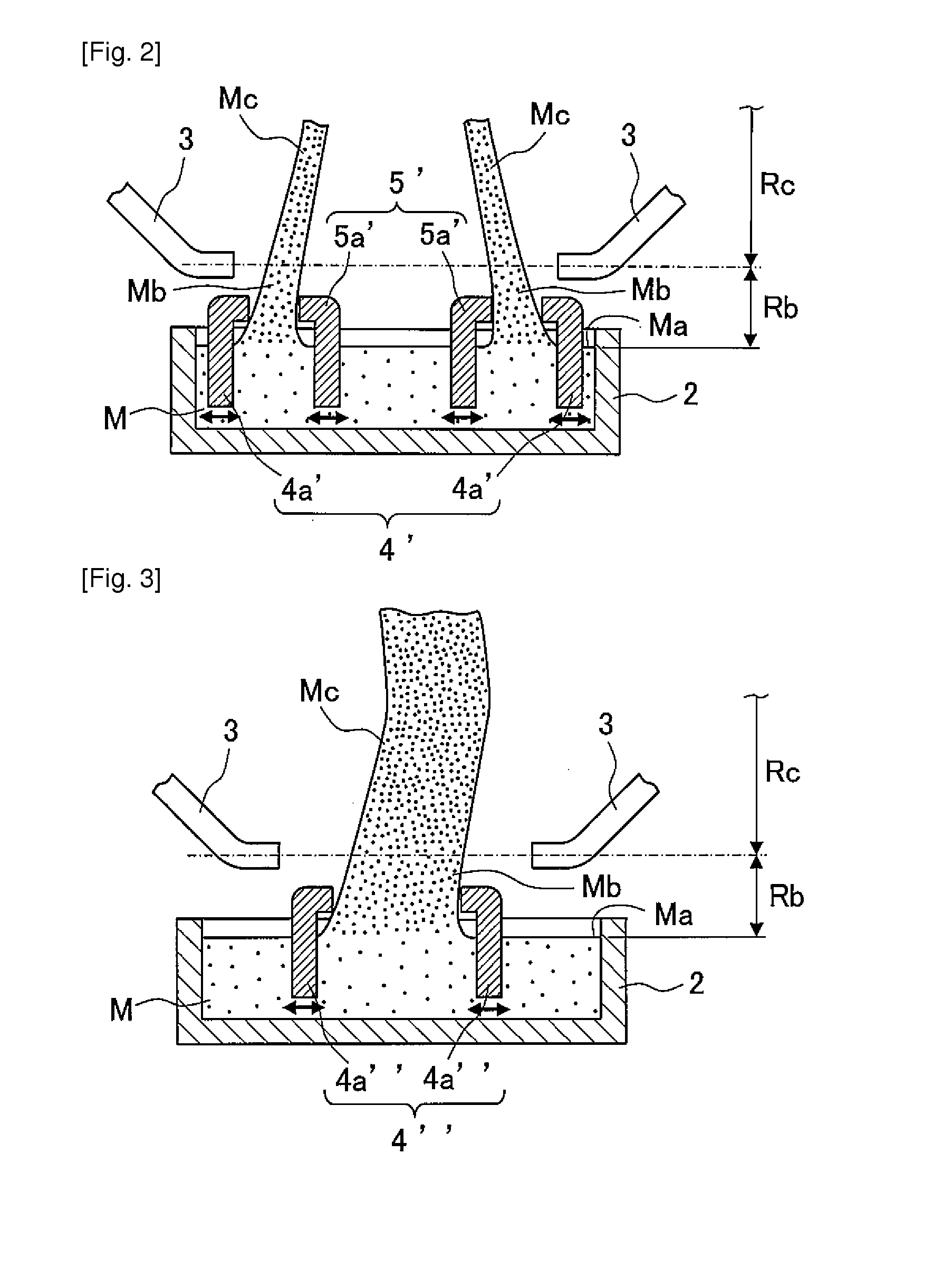
[0065]FIG. 8 is a perspective view showing an embodiment 2 of the manufacturing device of a casting of the present invention. Also, FIG. 9 is a view describing a state immediately after drawing out of molten metal from a molten metal bath using the manufacturing device shown in FIG. 8, and FIG. 9(a) is a vertical cross-sectional view thereof and FIG. 9(b) is an arrow view along line A2-A2 in FIG. 9(a). Also, FIG. 10 is a view describing a state where a part of molten metal drawn out from a molten metal bath using the manufacturing device shown in FIG. 8 is solidified, and FIG. 10(a) is a vertical cross-sectional view thereof and FIG. 10(b) is an arrow view along line B2-B2 in FIG. 10(a). Furthermore, FIG. 11 is a perspective view showing an embodiment 2 of a casting manufactured by the manufacturing device shown in FIG. 8.

[0066]A manufacturing device 10B of the embodiment 2 shown in FIG. 8 is different from the manufacturing device 10A of t...


PUM

PropertyMeasurementUnit
Timeaaaaaaaaaa

Abstract

There are provided a manufacturing method of a casting capable of easily manufacturing a casting having a complex form and of increasing the degree of freedom of form of the casting to be manufactured, a manufacturing device thereof and a casting. At the time of forming a casting by drawing out molten metal from a bath surface of a molten metal bath and solidifying the molten metal which has been drawn out, an outer contour unit configured from a plurality of outer contour defining members for defining the outer contour of a casting is arranged in a region between the bath surface of the molten meth bath and a solid region where the molten metal is solidified and the molten metal which has been drawn out from the bath surface is drawn out through a region determined by the outer contour unit, and the form of the casting is changed by moving at least one of the plurality of outer contour defining members according to the drawing out of the molten metal.

Description

BACKGROUND OF THE INVENTION[0001]1. Field of the Invention[0002]The present invention relates to a manufacturing method of a casting, a manufacturing device thereof, and a casting, and particularly, to a manufacturing method of a casting that uses a free casting method, a manufacturing device thereof, and a casting that is manufactured using the free casting method.[0003]2. Description of the Related Art[0004]Conventionally, a metallic product having a complex form is manufactured by filling melted metal (molten metal) into a mold having a cavity having a predetermined form and solidifying the molten metal in the mold.[0005]Incidentally, with a casting method that uses a mold, it is known that a casting defect such as solidification cracking, shrinkage cavity or porosity, for example, may occur because of restriction and solidification due to cooling from the inner wall surface of the cavity of the mold.[0006]Regarding such a problem, in recent years, techniques regarding casting me...

Claims


Application Information

Patent Timeline
IPC IPC(8): B22D11/041B22D11/124B22D11/14
CPCB22D11/041B22D11/124B22D11/145B22D11/006
Inventor SASAKI, YUFURUKAWA, YUICHIAMANO, NORIHIROYAOKAWA, JUNIWATA, YASUSHISUGIYAMA, YOSHIO
Owner TOYOTA JIDOSHA KK
Why Eureka
Try Eureka