Self-powered flashlight/lantern

a flashlight and lantern technology, applied in the direction of lighting support devices, lighting and heating apparatus, light source combinations, etc., can solve the problems of not always available or convenient, and the limitations of hands-free and hand-held use of prior art flashlights and/or lanterns

Inactive Publication Date: 2008-12-11
INNOVATIVE CONCEPTS
View PDF8 Cites 32 Cited by
  • Summary
  • Abstract
  • Description
  • Claims
  • Application Information

AI Technical Summary

Benefits of technology

[0006]One embodiment of the present invention is an illuminating device including several elements. The illuminating device includes a light source housing. The device also includes at least one LED located within the housing and a grip handle. The grip handle includes a first shell and a second shell, and the first shell and the second shell join together and define a collar at one end. The device also includes a rotatable shaft, defined on the light source housing. The shaft is coupled to the spindle on the grip handle of the housing. The collar rotates on the spindle to rotate the grip handle relative to the light source housing in a twisting...

Problems solved by technology

There are also several functional limitations for hands-free and hand-held uses associated with prior art flashlights and/or lanterns.
This is a...

Method used


Image

  • Self-powered flashlight/lantern
  • Self-powered flashlight/lantern
  • Self-powered flashlight/lantern

Examples


Embodiment Construction

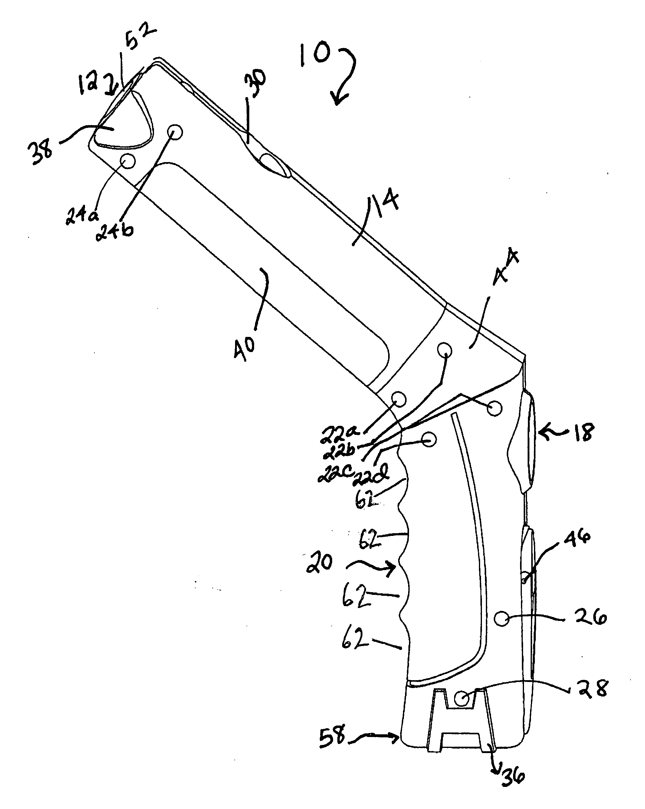
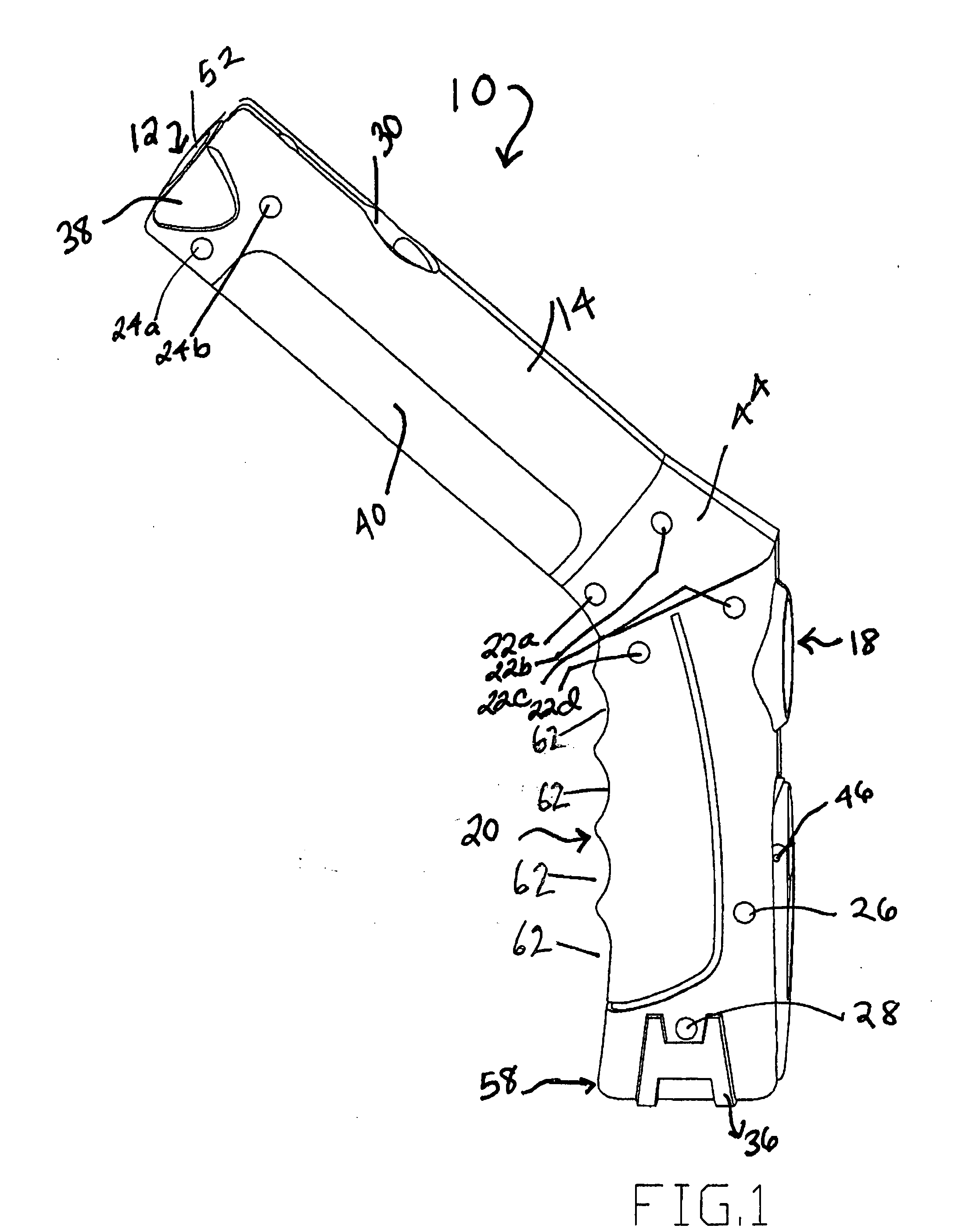
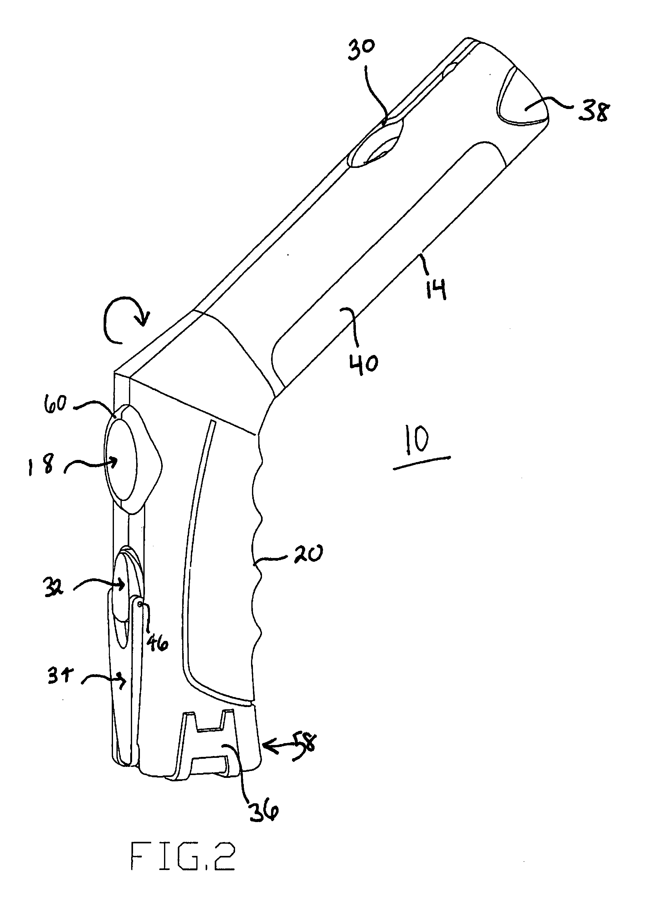
[0024]With reference to the figures, FIGS. 1-10 illustrate an illuminating device constructed in accordance with the present invention. An illuminating device 10 includes a headlamp 12, more clearly shown in FIG. 9. In this embodiment, the headlamp 12 comprises, for example, a single light bulb 52 which emits a direct beam of light. The headlamp 12 is located at the front end of illuminating device 10, and is mounted in an illuminator housing 14. The housing 14 of the illuminating device 10 has a concave divot 38 where the headlamp 12 is located and placed.

[0025]The housing 14, which is attached to a rotating member 44, includes a plurality of LEDs making up a lantern 40 of the illuminating device 10. The rear of the illuminating device 10 is shown in FIG. 5. As can be seen in this figure, a hook 30 is mounted in a recess 31 of the housing 14.

[0026]The handle 20 includes indentations 62 to provide an easy grip for a user on the illuminating device 10, as can be seen in FIGS. 1-4, 6 ...


PUM


Abstract

An illuminating device including a housing, at least one LED located within said housing, a grip handle, wherein the grip handle comprises a first shell and a second shell, wherein the first shell and the second shell join together, a rotatable shaft, coupled to the grip handle and to the housing, wherein the rotatable shaft comprises a spindle and a belt that rotates along the spindle to rotate the grip handle and the housing in a twisting motion against one another, an electric generating device received in a cavity of the grip handle, and an actuating device including a follower rotatably attached to the grip handle, including a handle pivotally attached to the follower for rotating the follower relative to the grip handle, and including a knob rotatably attached to the handle, to allow the handle to be rotated relative to the grip handle, wherein the actuating device and the electric generating device generate electric energy to energize the illuminating device.

Description

FIELD OF THE INVENTION[0001]The present invention relates to a self-powered illuminating device, and more particularly, a self-powered illuminating device with flashlight and lantern illuminating members connected by a spindle and collar coupling to a deflectable handle to facilitate ergonomic and / or stable use of the same under a variety of conditions.BACKGROUND OF THE INVENTION[0002]Typical illuminating devices are lanterns and / or flashlights that require either batteries or an AC voltage source. The inability to adjust the position and orientation of a flashlight and / or a lantern can be inconvenient. Typically, lanterns are designed to be placed on a table for illumination of an area such as a work area, for example, for reading, eating or the like. Alternatively lanterns may be hung or placed on a high object.[0003]In principal, ordinary flashlights may be used for work area illumination. In such uses, typically, the user places a flashlight in a stable position, aimed as closel...

Claims


Application Information

Patent Timeline
IPC IPC(8): F21L4/00F21S4/00F21V19/02F21V21/088F21V21/096
CPCF21L4/04F21L4/08F21L13/06F21V21/0965F21V21/30F21V21/406F21Y2101/02F21Y2113/00F21Y2115/10
Inventor CANINO, SERAFINO S.GELORMINO, SCOTT
Owner INNOVATIVE CONCEPTS
Why Eureka
Try Eureka