Root cutting shovel

a shovel and root technology, applied in the field of shovels, can solve the problems of time-consuming and physical demanding, and the current shovels do not adequately address the problem associated, and achieve the effect of quick and easy digging through root-infused ground

Inactive Publication Date: 2008-12-18
BAKER WILLIAM J
View PDF14 Cites 24 Cited by
  • Summary
  • Abstract
  • Description
  • Claims
  • Application Information

AI Technical Summary

Benefits of technology

[0006]The primary object of the present invention is to provide a root cutting shovel that permits a person to quickly and easily dig a hole through a root-infused ground.
[0011]To use the present invention, a user inserts the tip of the head into a ground surface desired to be dug into. Then, the user exerts a predetermined amount of force on the head via the handle to push the head deeper and deeper into the ground. If roots are located within the ground, the serrated teeth located along the first and second edges of the head act to grind and cut through the roots, thereby permitting a user to easily dig through the root-infused ground. If a greater amount of force is necessary, the user may place his or her foot on one or both of the flanges and step down on one or both of the flanges in order to provide a greater downward force on the head of the shovel.

Problems solved by technology

Although there have been advancements in the structure of the shovel, which in turns affect the purpose of the shovel, current shovels do not adequately address the problem associated with digging in a ground infused with roots.
Although a person may use a traditional shovel to repeatedly hit the roots, thereby weakening and eventually breaking the roots, the process of doing so is not only time-consuming, but also very physically demanding.

Method used


Image

  • Root cutting shovel
  • Root cutting shovel
  • Root cutting shovel

Examples


Embodiment Construction

[0018]For purposes of describing the preferred embodiment, the terminology used in reference to the numbered components in the drawings is as follows:

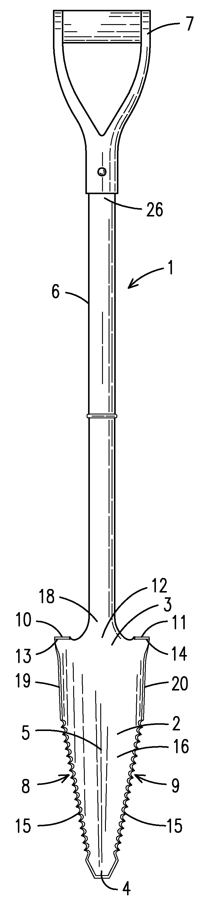
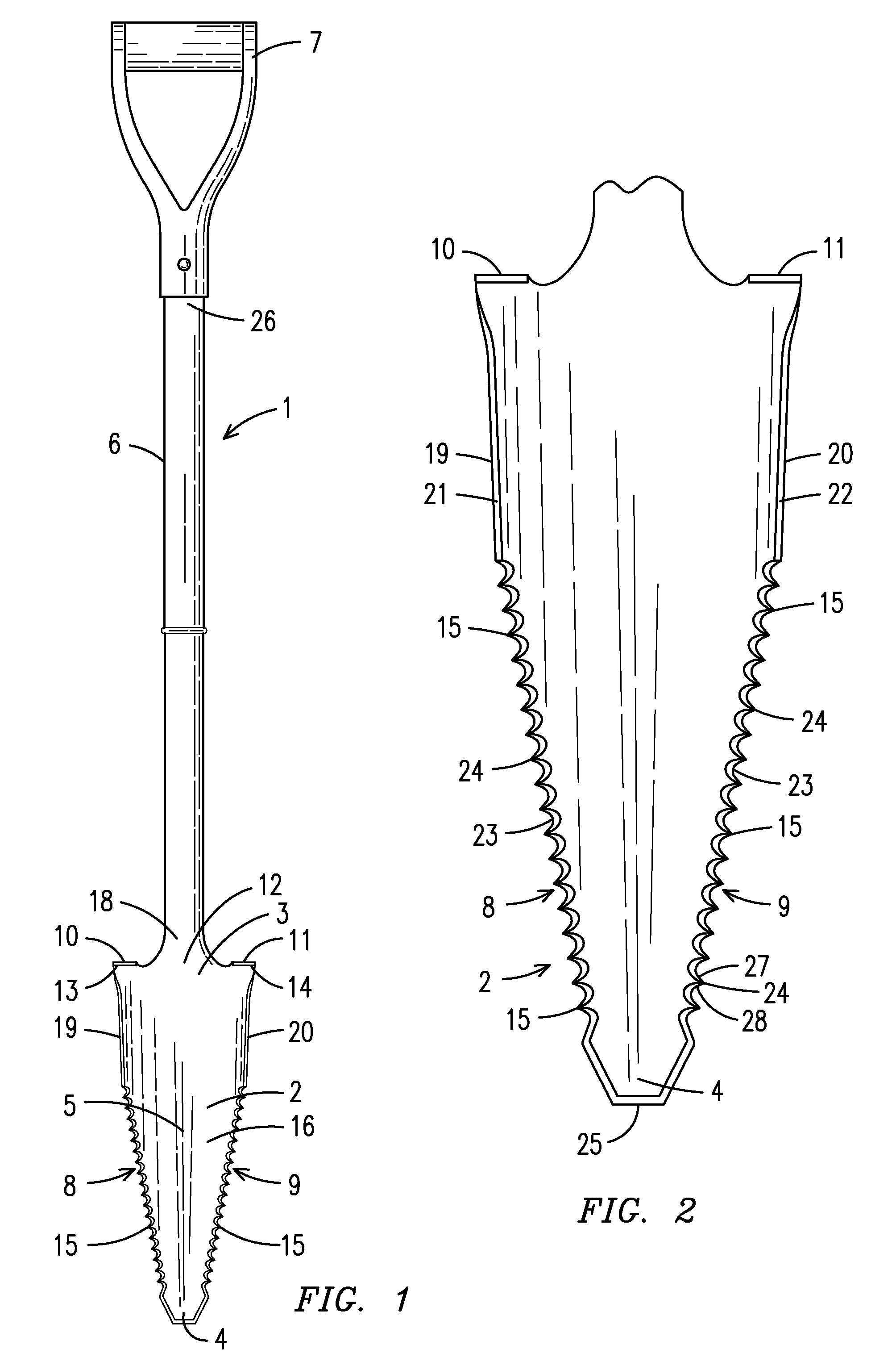
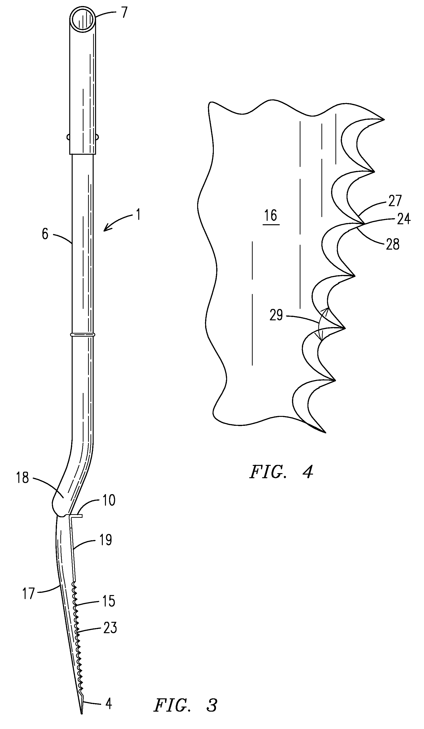
 1. root cutting shovel, generally 2. head 3. top 4. tip 5. retaining portion 6. handle 7. grip 8. first edge 9. second edge10. first flange11. second flange12. center13. first end14. second end15. teeth16. front face17. rear face18. handle distal end19. first linear portion20. second linear portion21. first linear portion edge22. second linear portion edge23. tooth edge24. apex25. tip edge26. handle proximal end27. tooth first side28. tooth second side29. angle

[0019]With reference to FIG. 1, a front view of a root cutting shovel of the present invention is shown. The root cutting shovel, generally 1, includes a head 2 having a front face 16, a top 3 and a tip 4 wherein the head 2 is secured to a distal end 18 of an elongated handle 6, preferably at a center 12 of the top 3. The head 2 is of a predetermined size and shape is preferably...


PUM


Abstract

A root cutting shovel (1) having a concave head (2) of a predetermined size and shape having a top (3) and a tip (4) wherein the head (2) has a front face (16) and a rear face (17). The head top (3) has a first end (13) and a second end (14) and a center (12) located between the first and second ends (13 and 14). A first edge (8) extends from the head first end (13) to the tip (4) while a second edge (9) extends from the head second end (14) to the tip (4). A plurality of serrated teeth (15) extend along the first and second edges (8 and 9) wherein each tooth (15) has a first side (27) and a second side (28) which join together at a predetermined angle (29), which is approximately sixty degrees. An elongated handle (6) is secured to the head top center (12) and flanges (10 and 11) are located on either side of the handle (6) and extend away from the head front face (16).

Description

BACKGROUND OF THE INVENTION[0001]This invention relates to shovels, more particularly, a root cutting shovel that permits a person to quickly and easily dig a hole through a root-infused ground.[0002]Shovels are the preferred tool of choice when removing a small amount of soil, dirt, debris and other items from a ground surface. Most also have a predetermined concave area on a shovel head to hold the soil, dirt, debris, etc., hereinafter referred to as a load, and permit a person to transport the load from one location to another. Over time, shovels have become modified to perform a variety of tasks in addition to removing and moving a load. For instance, various types of shovels have different structural elements to permit a user to pierce through a ground surface, scoop a larger load, dig a wider hole and the like.[0003]Although there have been advancements in the structure of the shovel, which in turns affect the purpose of the shovel, current shovels do not adequately address th...

Claims


Application Information

Patent Timeline
Patent Type & Authority Applications(United States)
IPC IPC(8): A01B1/04
CPCA01B1/04
Inventor BAKER, WILLIAM J.
Owner BAKER WILLIAM J
Why Eureka
Try Eureka