Gasifier and gasifier system for pyrolizing organic materials

a gasifier and organic material technology, applied in gasifier mechanical details, furnaces, muffle furnaces, etc., can solve the problems of inability to repair the inside vertical auger, tendency to burn up at the tip, and none of these patents deal with horizontal auger systems, etc., to achieve easy maintenance, low cost of operation, and low construction cost

a gasifier and organic material technology, applied in gasifier mechanical details, furnaces, muffle furnaces, etc., can solve the problems of inability to repair the inside vertical auger, tendency to burn up at the tip, and none of these patents deal with horizontal auger systems, etc., to achieve easy maintenance, low cost of operation, and low construction cost

US20090000195A1Inactive Publication Date: 2009-01-01HEAT TRANSFER INT

Image

  • Gasifier and gasifier system for pyrolizing organic materials
  • Gasifier and gasifier system for pyrolizing organic materials
  • Gasifier and gasifier system for pyrolizing organic materials

Examples


Embodiment Construction

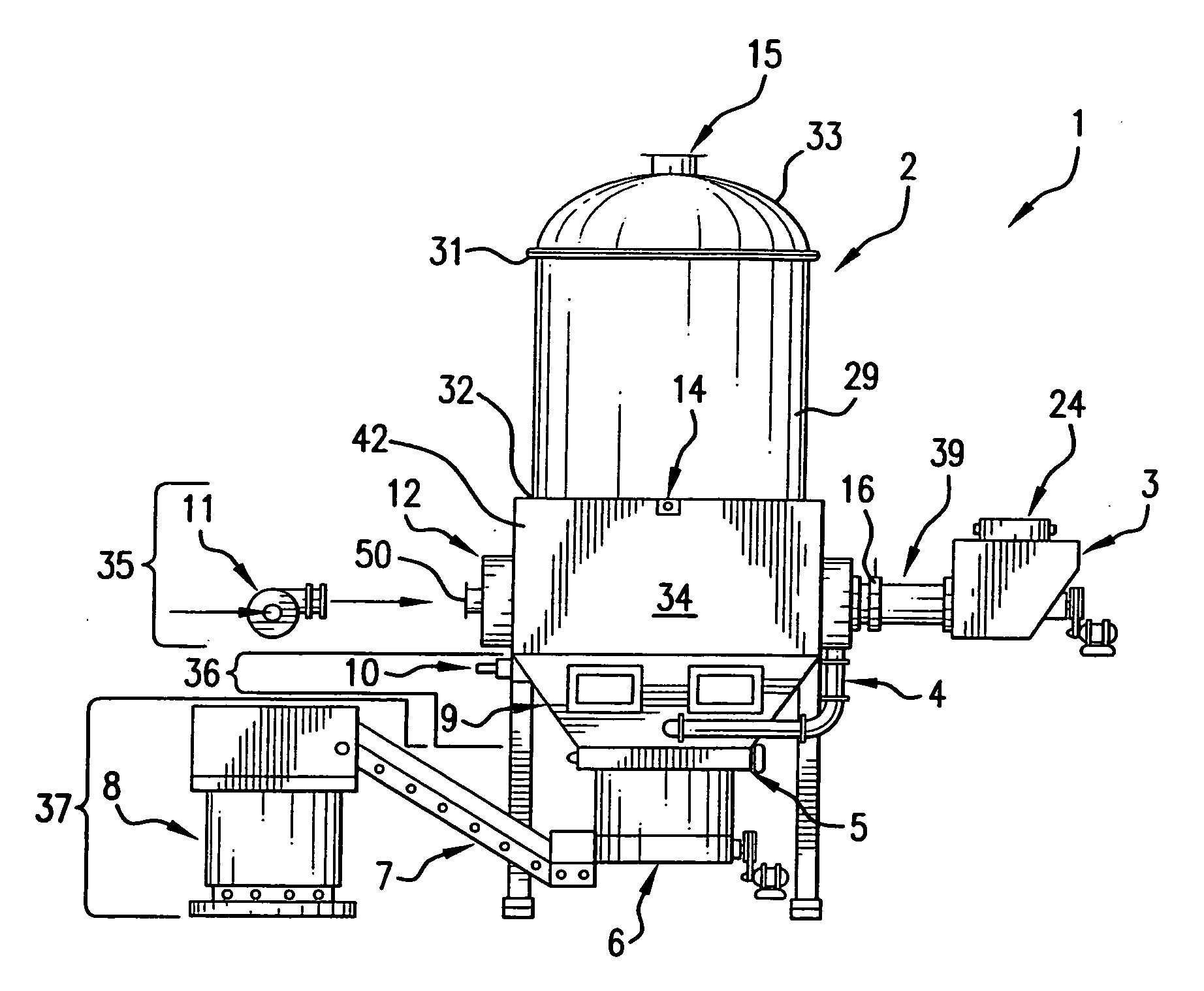
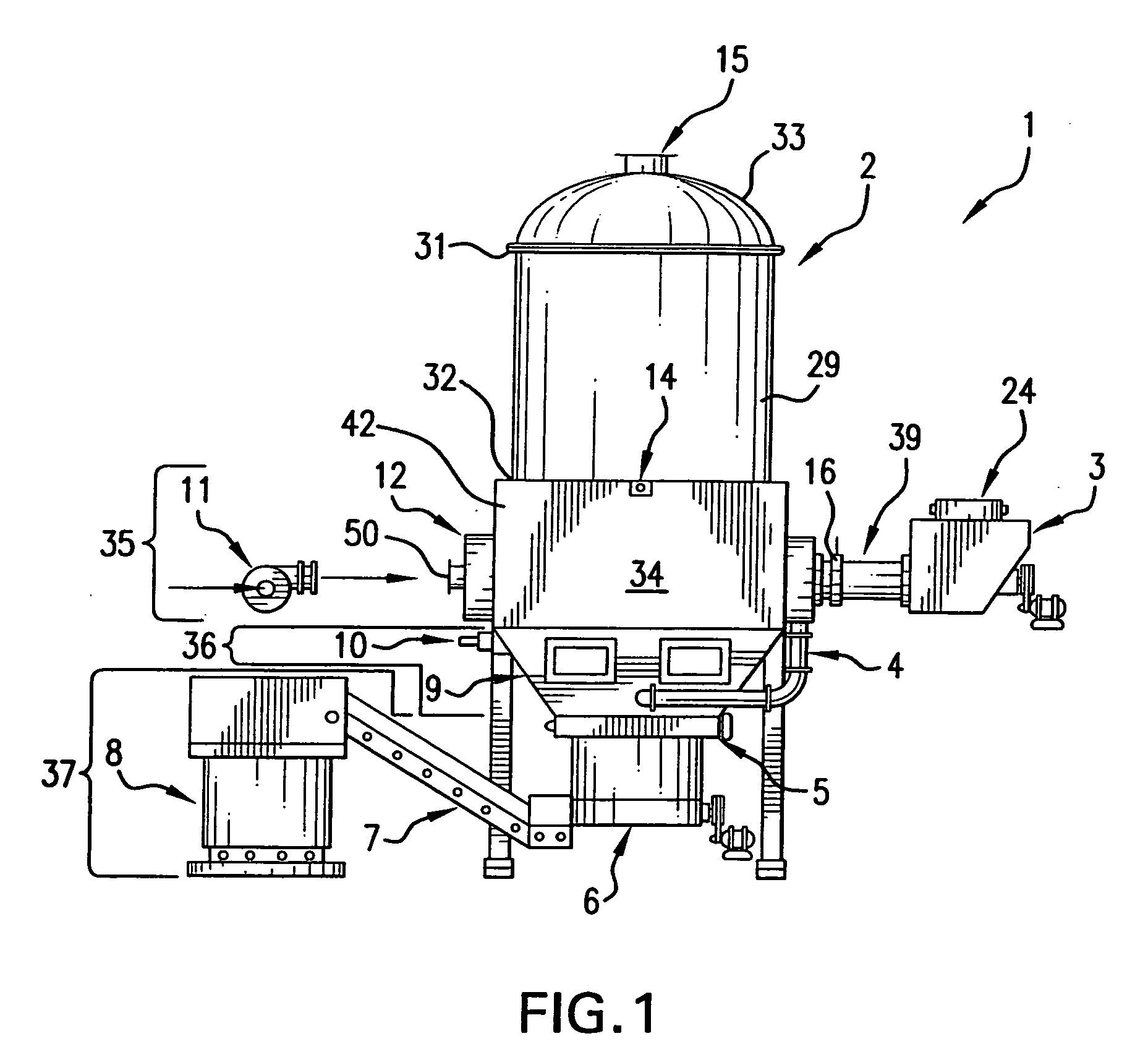
[0024]Turning now to FIG. 1 wherein there is shown a full front view of a gasifier system 1 of this invention showing a refractory lined combustion chamber 2 having a cylindrical housing 29 wherein the cylindrical housing has sidewalls 30 that are completely lined with a refractory material 27, a feed hopper 3, a litter feed conveyor 24, a tuyere air manifold 4, an oscillating ceramic grate 5, an ash auger 6, an ash lift conveyor 7, an enclosed ash dumpster 8, a tuyere plenum 9, a lance ignition burner 10, a combustion air fan 11, a feed tube 12, a feed tube housing 13, a pile control detector 14, a syngas exit duct 15, and a control valve 16. The cylindrical housing 29 has a top 31 and a bottom 32, the top 31 being surmounted by a monolithic dome 33 having the syngas exit duct 15 mounted thereon (See FIG. 1).

[0025]The dome 33 has a hemi-elliptical section comprising a height to diameter ratio of at least 1 to 2 and the dome 33 is also completely lined with a refractory material (no...


PUM

PropertyMeasurementUnit
heightaaaaaaaaaa
diameteraaaaaaaaaa
areaaaaaaaaaaa

Abstract

A gasifier and gasifier system based on the gasifier, which contains as a major component, a novel feed system for feeding organic materials into the burn pile of the gasifier. The gasifier feed system is a horizontal auger driven feed system that feeds directly through a ceramic elbow into the furnace without having to auger the feed through significant vertical elevations.

Description

[0001]This application claims priority from U. S. Provisional Patent application ser. no. 60 / 937,309, filed Jun. 27, 2007.[0002]The invention disclosed and claimed herein is a gasifier and gasifier system based on the gasifier, which contains as a major component, a novel feed system for feeding organic materials into the burn pile of the gasifier.[0003]The invention is useful for gasifying solid organic materials and using such gasified products for conversion to thermal energy.[0004]Materials that can be gasified using this invention include, among other materials, biomass materials, such as forestry and agricultural residues, industrial waste materials, such as saw mill pulp and paper products, hydrocarbon based products and plastics, and the like.BACKGROUND OF THE INVENTION[0005]It has been known in the art for a long time to use industrial and agricultural solid organic by-products, such as forestry an agricultural residue and the like, as potential sources of large amount of c...

Claims


Application Information

Patent Timeline
01 Jan 2009
Publication
US20090000195A1
IPC
C10J3/30
CPC
C10J3/30; C10J3/40; C10J3/74; C10J2200/09; C10J2300/0956; C10J2300/0916; C10J2300/092; C10J2300/0946
Inventors
GRAHAM, ROBERT G.