Fuse element and manufacturing method thereof

a manufacturing method and fuse element technology, applied in the manufacture of emergency protective devices, electrical devices, protective switch operating/release mechanisms, etc., can solve the problems of longer time required to activate the breaking action of the fuse element, shorten the time required for the fuse element to reach the fuse, and the fuse element supported on the ceramic substrate often requires longer time to reach the fuse. , to achieve the effect of high current and high temperature operation

Inactive Publication Date: 2009-01-08
CYNTEC
View PDF48 Cites 16 Cited by
  • Summary
  • Abstract
  • Description
  • Claims
  • Application Information

AI Technical Summary

Benefits of technology

[0010]It is therefore an aspect of the present invention to provide a fuse element and a manufacturing method of the fuse element to sustain a high current and high temperature operation without the limitation of slower fuse breaking reaction as that generally encountered in the above-discussed conventional techniques such that the difficulties and limitations can be overcome.

Problems solved by technology

Even though there are many types of fuse elements implemented as over current protection, there are still technical limitations and difficulties as now available in the marketplace to provide fuse elements configured a micro-chip.
Due to this higher thermal conductivity, a fuse element supported on a ceramic substrate often requires longer time to reach a fuse temperature to break the circuit for over-current protection.
However, similar to the first type of fuse elements, longer time is required to activate a fuse breaking action due to a higher thermal conductivity of the glass substrate.
It is often required to use a thicker layer for fuse thus causes higher resistance and higher power consumption.
However, such substrate lacks characteristics of high temperature and high current reliabilities that are often required for many applications of over-current protections.
The scopes of fuse elements using fiberglass as supporting substrates are therefore greatly limited.
However, similar to the fuse elements that supported on the fiberglass substrates, the polymer layer is not stable in a high temperature.
Therefore, the conventional thin-film fuse elements supported on the aluminum oxide substrate have limited scope applications due to the limited capacity to sustain high temperature and high current operations.
Furthermore, a fuse layer and the substrate are not securely adhered to the heat insulation layer due to both surfaces of the heat insulation layer surface are formed smooth surfaces.

Method used


Image

  • Fuse element and manufacturing method thereof
  • Fuse element and manufacturing method thereof
  • Fuse element and manufacturing method thereof

Examples


Embodiment Construction

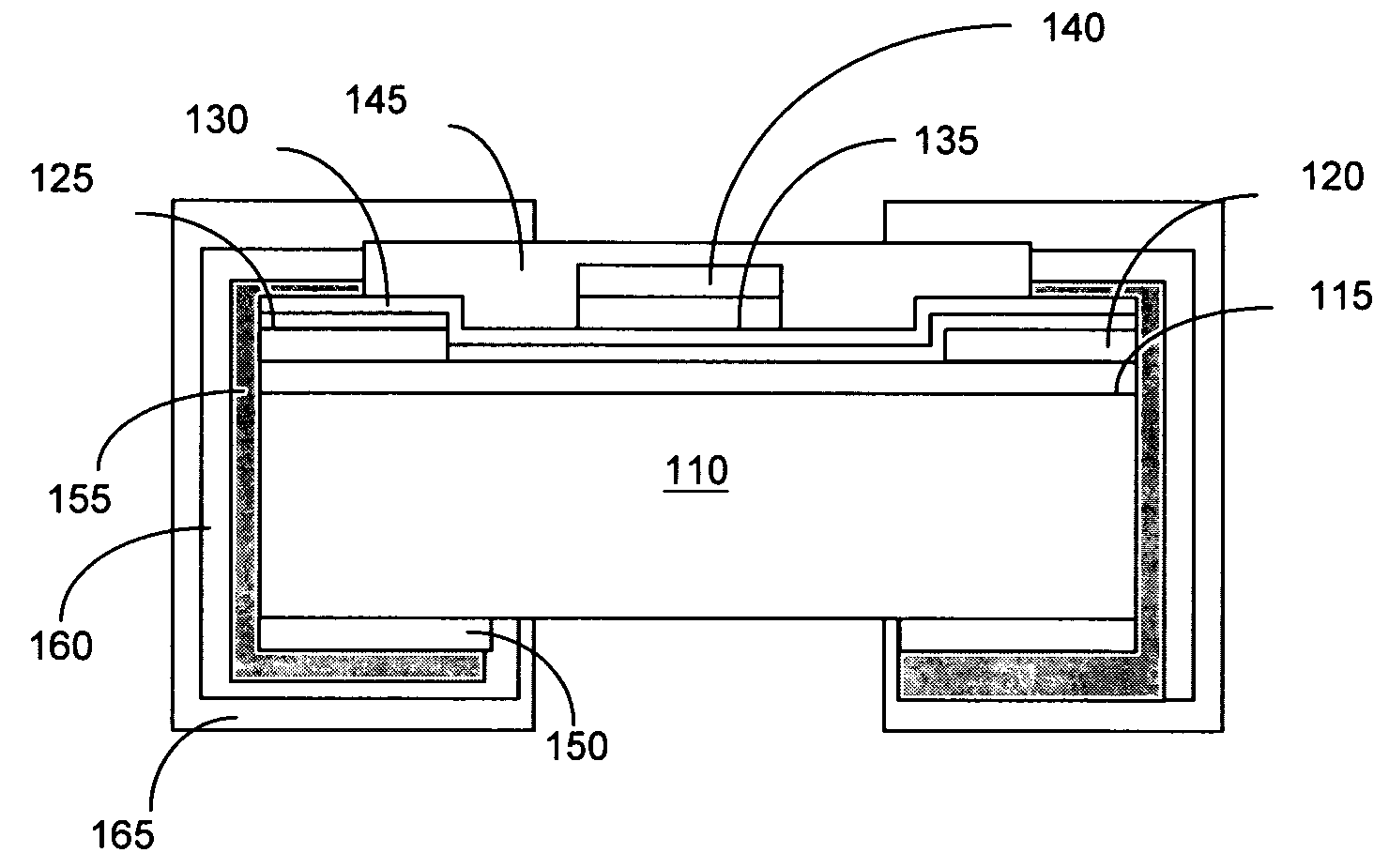
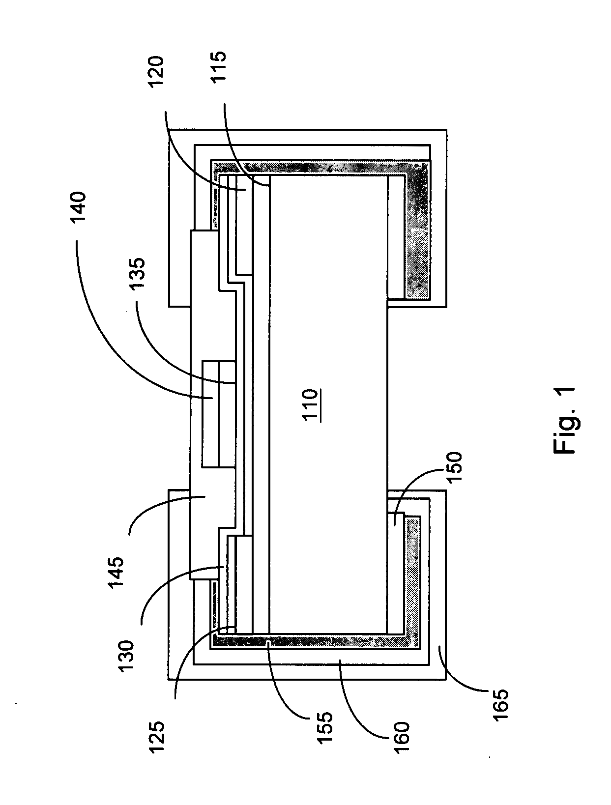
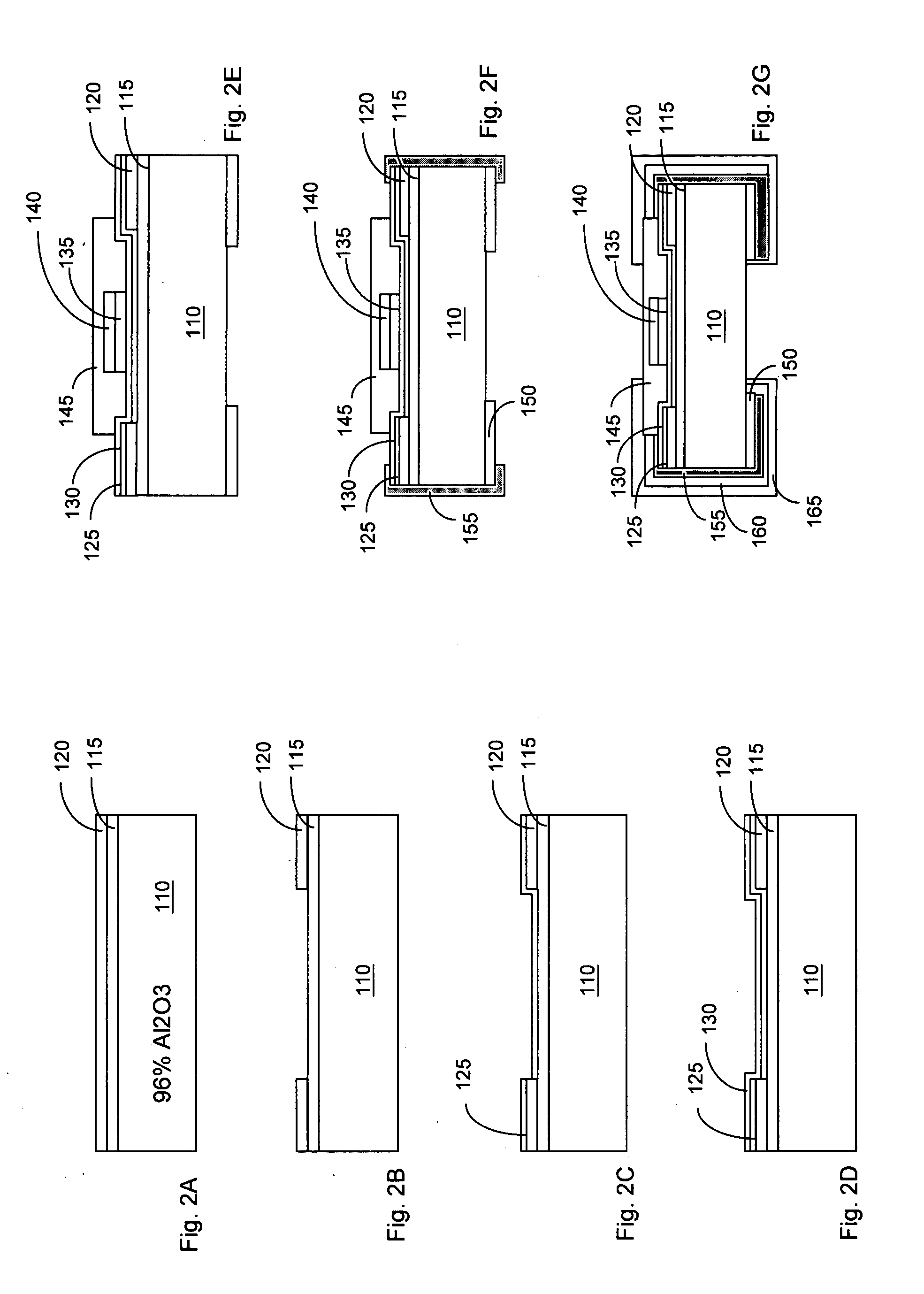
[0019]Referring to FIG. 1, a fuse element 100 according to the present invention comprises a substrate 110, a heat insulation layer 115, a pair of copper terminal 120, a first seed layer 125, a fuse layer 130, a buffer layer 135, an accelerated layer 140, a protective layer 145, a bottom terminal layer 150, a second seed layer 155, and side terminal layers 160 and 165. The protective layer 145 is disposed above the heat insulation layer 115. The fuse layer 130 is disposed between the heat insulation layer 115 and the protective layer 145. The fuse element is manufactured with a thin film technology.

[0020]The fuse element 100 begins with the substrate 110 for supporting the other elements of the fuse element 100. In the embodiment, the material of the substrate 110 is an aluminum oxide (Al2O3). Other material for the substrate 110 includes, but not limited to, glass. The substrate 110 includes a top surface 1101, a bottom surface 1102 opposite to the top surface 1101, and side surfac...


PUM


Abstract

A fuse element comprises a substrate having a top surface, a bottom surface opposite to said top surface, and side surfaces, a heat insulation layer including a first surface and a second surface opposite to said first surface, said first surface of said heat insulation layer disposed on said top surface of said substrate, and said second surface having a surface roughness, a protective layer disposed above said heat insulation layer, and a fuse layer disposed between said heat insulation layer and said protective layer.

Description

BACKGROUND OF THE INVENTION[0001]1. Field of the Invention[0002]This invention relates generally to a device configuration and manufacturing method for providing a fuse element. More particularly, this invention relates to an improved device configuration and manufacturing method for providing a fuse element by using resin coated copper (RCC) foil.[0003]2. Description of the Prior Art[0004]Even though there are many types of fuse elements implemented as over current protection, there are still technical limitations and difficulties as now available in the marketplace to provide fuse elements configured a micro-chip. Specifically, there are basically following types of fuse elements configured as chips.[0005]The first type of fuse elements is fuse elements that are supported on a ceramic substrate. This type of fuse elements has the benefit of reliable operation at a higher operation because the ceramic substrate can sustain higher temperature. However, the thermal conductivity of th...

Claims


Application Information

Patent Timeline
Patent Type & Authority Applications(United States)
IPC IPC(8): H01H85/04H01L21/44
CPCH01H69/022H01H85/006H01H2085/0414H01H85/046H01H85/11H01H85/0418
Inventor WANG, CHUNG-HSIUNGSONG, YU-LIANGSONG, QING-FENGLI, YU-QIAOQIU, JIAN-DALIU, MENG
Owner CYNTEC
Why Eureka
Try Eureka