Video signal processing device, video signal processing method and video signal processing program

a video signal processing and video signal processing technology, applied in the field of video signal processing devices, video signal processing methods and video signal processing programs, can solve the problems of deterioration of visibility, lower image sharpness, and high compression rate, and achieve high-quality reproduction, not suppressing visibility deterioration, and suppressing noise components

Inactive Publication Date: 2009-01-22
SONY CORP
View PDF15 Cites 6 Cited by
  • Summary
  • Abstract
  • Description
  • Claims
  • Application Information

AI Technical Summary

Benefits of technology

[0024]On the other hand, the technique disclosed in the invention of Patent Document 1 adaptively suppresses noise components in an input video signal according to the amount of noise in the same signal for compression coding, thus providing a high-quality reproduced image. However, this technique cannot suppress the deterioration in visibility while at the same time providing reduced transmission data size.
[0025]The present invention has been made in light of the foregoing problems to propose a monitoring camera system capable of reducing the deterioration in visibility while at the same time providing reduced transmission data size.
[0026]To solve the foregoing problems, the present invention includes a compression section configured to compress video and a noise reduction section configured to reduce noise in video data by a predetermined amount according to the size of the video data transmitted onto the network. The present invention can provide reduced noise according to the transmission data size, thus suppressing the deterioration in visibility at a low bit rate.
[0027]The present invention can realize a video signal processing device, a video signal processing method and a video signal processing program capable of suppressing visibility deterioration caused by image quality degradation irrespective of the data size transmitted onto a network.

Problems solved by technology

The compression at a higher compression rate involves several problems, including lower image sharpness and deteriorated visibility resulting from block noise and false color.
This makes it impossible to achieve data compression at an exceedingly high compression rate.
In particular, an image superposed with noise components will suffer quality degradation if compressed at higher compression rates.
The reduction of image resolution leads to poor visibility of small objects, fine patterns and others in the image.

Method used


Image

  • Video signal processing device, video signal processing method and video signal processing program
  • Video signal processing device, video signal processing method and video signal processing program
  • Video signal processing device, video signal processing method and video signal processing program

Examples


Embodiment Construction

[0043]An embodiment of the present invention will be described in detail below with reference to the accompanying drawings.

(1) Overall Configuration of the Monitoring Camera System

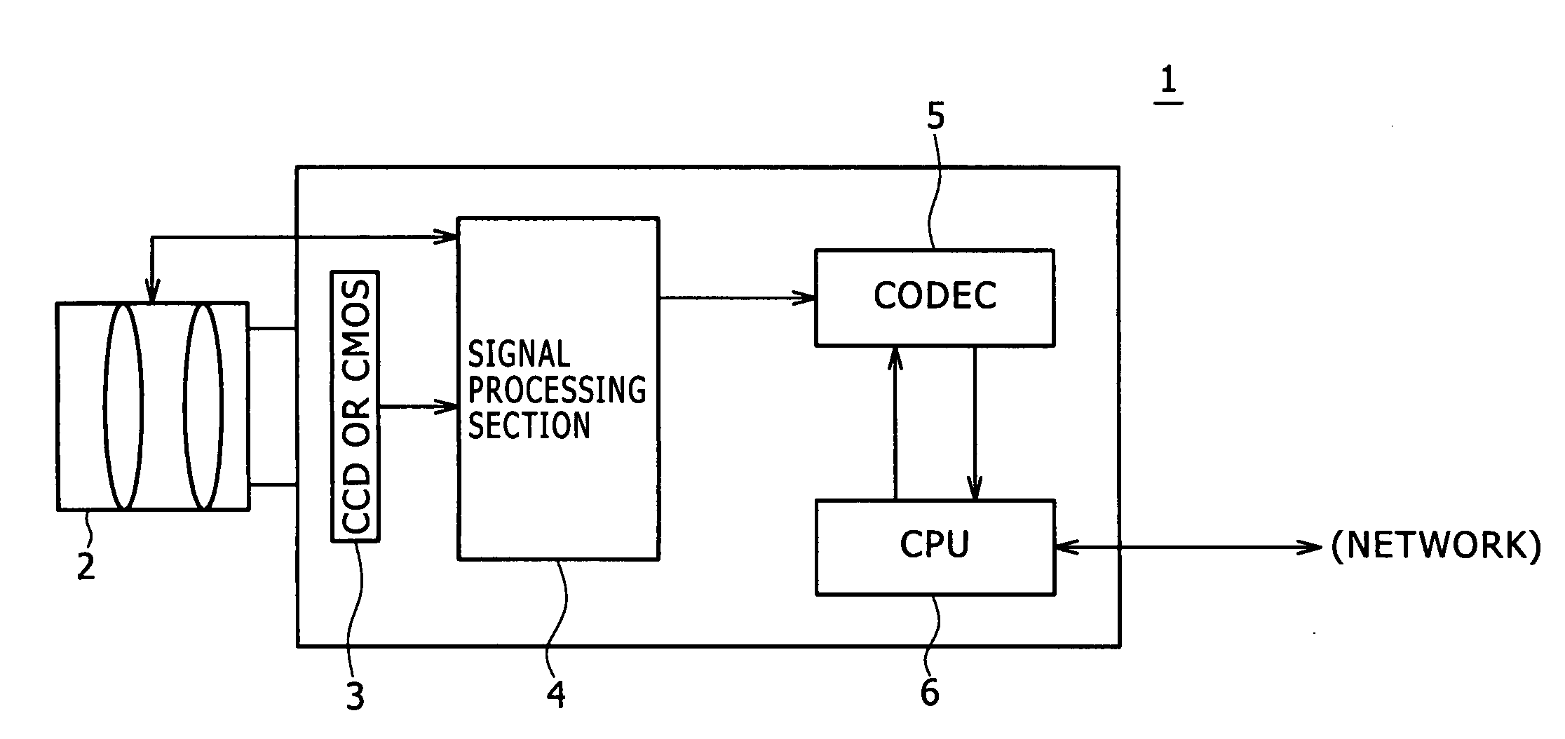
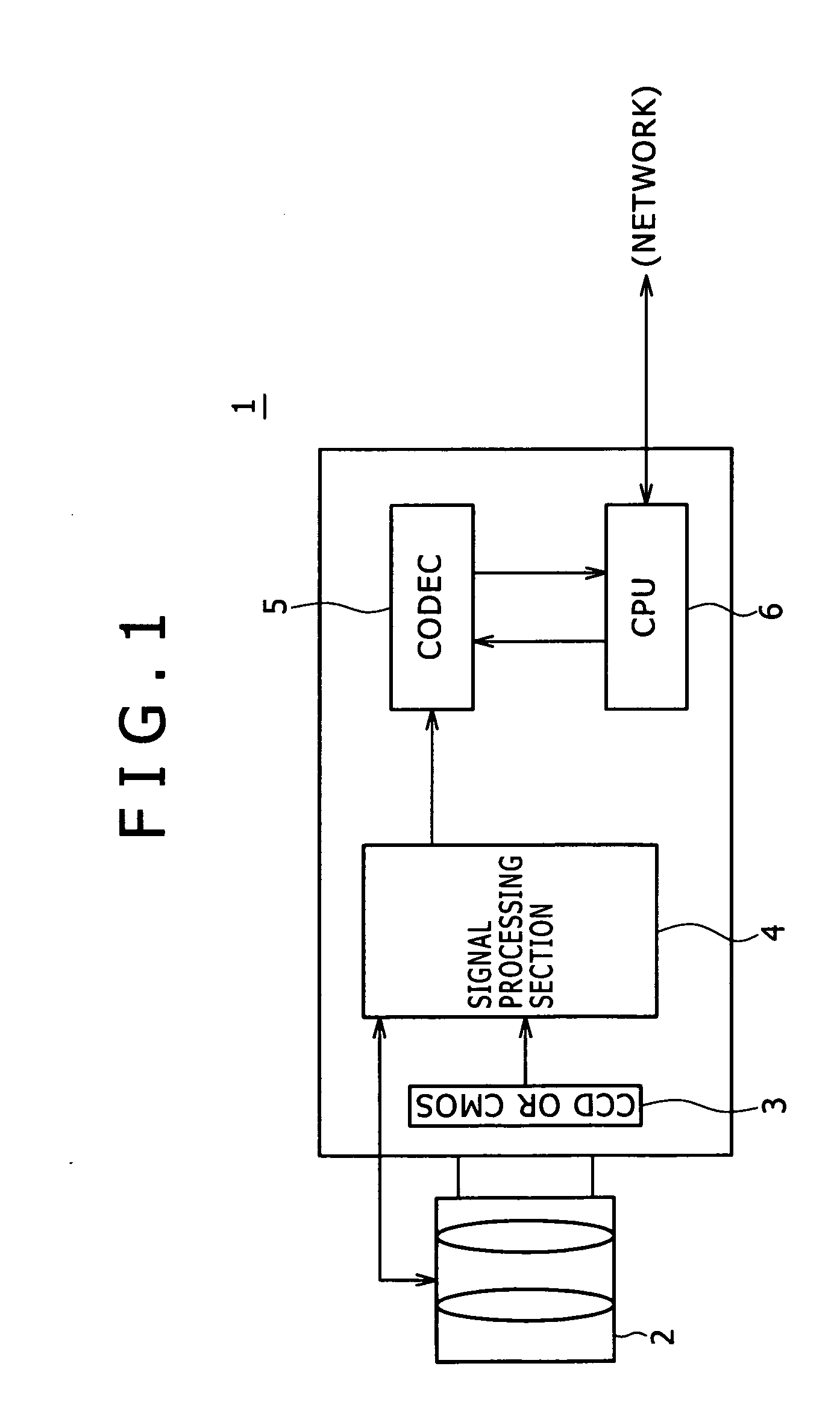
[0044]As illustrated in FIG. 3, a monitoring camera system 10 according to the present embodiment includes an image input section 11, signal processing section 12, codec 13 and CPU 16. The image input section 11 includes components which are not shown such as a lens and CCD (Charge Coupled Device) or CMOS (Complementary Metal Oxide Semiconductor) sensor. The same section 11 is connected to the signal processing section 12. The same section 12 is connected to the codec 13. The codec 13 is connected to the CPU 16.

[0045]The image input section 11 corresponds to the lens 2 and CCD or CMOS sensor 3 in FIG. 1. The same section 11 supplies image data for the captured image to the signal processing section 12. The signal processing section 12 corresponds to the signal processing section 4 in FIG. 1. The same secti...


PUM


Abstract

A video signal processing device for compressing input video and transmitting compressed video data onto a network, the video signal processing device including a compression section configured to compress the video, and a noise reduction section configured to reduce noise in video data by a predetermined amount of noise reduction according to the size of the video data transmitted onto the network.

Description

CROSS REFERENCES TO RELATED APPLICATIONS[0001]The present invention contains subject matter related to Japanese Patent Application JP 2007-176650 filed with the Japan Patent Office on Jul. 4, 2007, the entire contents of which being incorporated herein by reference.BACKGROUND OF THE INVENTION[0002]1. Field of the Invention[0003]The present invention relates to a video signal processing device, a video signal processing method and a video signal processing program, and relates, for example, to a video signal processing device, a video signal processing method and a video signal processing program for providing reduced noise in input video data and smaller transmission data size which are suitable for application to a monitoring camera system.[0004]2. Description of the Related Art[0005]Previously, so-called analog camera systems were in common use as monitoring camera systems. Each of such systems has a video tape recorder or other video recording device connected to a camera with a ...

Claims


Application Information

Patent Timeline
Patent Type & Authority Applications(United States)
IPC IPC(8): H04N5/00H04N19/00H04N1/41H04N7/26H04N19/117H04N19/132H04N19/134H04N19/136H04N19/146H04N19/162H04N19/196H04N19/423H04N19/625H04N19/80
CPCG06T5/002G06T5/20G06T5/50G06T2207/10016G06T2207/20182G06T2207/30232H04N19/85H04N19/102H04N19/117H04N19/132H04N19/146H04N19/162H04N19/80H04N19/172
Inventor HAYASHI, KAZUYOSHI
Owner SONY CORP
Why Eureka
Try Eureka