In-Ear Phone

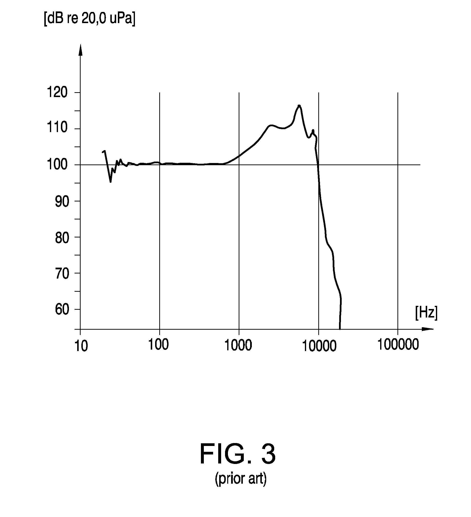
a technology for in-ear phones and phones, applied in the field of in-ear phones, can solve the problems of not being able to reproduce frequencies higher than 10000 hz very well, and achieve the effect of inhibiting external noise and disturbances, high frequency, and high quality reproduction

Inactive Publication Date: 2008-08-21
KONINKLIJKE PHILIPS ELECTRONICS NV
View PDF21 Cites 7 Cited by
  • Summary
  • Abstract
  • Description
  • Claims
  • Application Information

AI Technical Summary

Benefits of technology

[0013]The provision of the characteristic features according to the invention creates the advantage that sound is emanated directly into the auditory canal. Thus a high quality reproduction of high frequencies is achieved.
[0014]It is advantageous when the in-ear phone comprises means for sealing the auditory channel. Thereby the advantage is achieved that external noise and disturbances can be inhibited very effectively.
[0015]It is further advantageous, when the speaker driver is partially covered by a housing. This measure provides the advantage that the driver can be positioned very easily in the auditory canal and that a good acoustical function is achieved.
[0016]Yet another preferred embodiment of the invention is provided with an in-ear phone, wherein the housing seals the auditory canal in an operating position of the in-ear phone. Thus the advantage is provided that producing of the in-ear phone is simplified since the sealing function and the function of positioning the speaker driver as well as providing a good acoustical function is realized by means of one item of hardware.
[0017]Finally it is advantageous, when the area of the sound emanating area is larger than an area of a cross section of the auditory canal, which cross section is essentially parallel to the eardrum. This measure provides the advantage of an excellent reproduction of sound, since the sound emanating area of the speaker driver is enlarged very much with regard to the eardrum.

Problems solved by technology

It is a disadvantage of the known in-ear phone that the reproduction of high frequencies is not optimal, since the volume A and the opening B constitute a low-pass filter for sound waves produced by the speaker driver 2.
As one can clearly see in FIG. 3 it is a major disadvantage of the known embodiment that frequencies higher than 10000 Hz are not reproduced very well.

Method used


Image

  • In-Ear Phone
  • In-Ear Phone
  • In-Ear Phone

Examples


Embodiment Construction

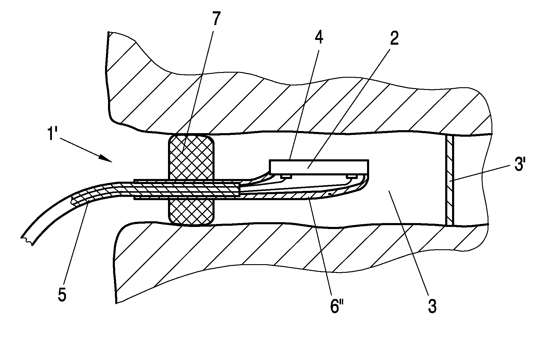
[0025]FIG. 4 shows an in-ear phone 1 according to the invention. The in-ear phone 1 comprises a speaker driver 2. The speaker driver 2 is of an oval form and disk-shaped. Alternatively, the speaker driver 2 may be of a rectangular or a square shape as well. The speaker driver 2 can be inserted into an auditory canal 3 of a user's ear. When the in-ear phone 1 is positioned in its operating position within the auditory canal 3, the direction of the axis a1 of the speaker driver 2 is substantially perpendicular to the direction of a longitudinal axis a2 of the auditory canal 3. This means that the plane of the sound emanating area 4 is substantially parallel to the axis a2 of the auditory canal 3.

[0026]According to a preferred embodiment of the invention the area of the sound emanating area 4 is larger than the area of a cross section of the auditory canal 3, which cross section is essentially parallel to the eardrum 3′. The measures mentioned in this paragraph achieve the advantage of...


PUM


Abstract

An in-ear phone (1) comprising a speaker driver (2) which is insertable into an auditory canal (3), wherein the direction of the axis (a1) of the speaker driver (2) is substantially perpendicular to the direction of the longitudinal axis (a2) of the auditory canal (3) in a mounted position of the in-ear phone (1), in which mounted position the speaker driver (2) is inserted into the auditory canal (3), and wherein a sound emanating area (4) of the speaker driver (2) extends at least partially directly into the auditory canal (3).

Description

FIELD OF THE INVENTION[0001]The invention relates to an in-ear phone comprising a speaker driver which is insertable into an auditory canal, wherein the direction of the axis of the speaker driver is substantially perpendicular to the direction of the longitudinal axis of the auditory canal in a mounted position of the in-ear phone, in which mounted position the speaker driver is inserted into the auditory canal.BACKGROUND OF THE INVENTION[0002]In-ear phones (also known as “canal-phones”) are placed inside the auditory canal of a user's ear, positioning them closer to the eardrum than other types of headphones.[0003]An in-ear phone as mentioned in the first paragraph is known from document U.S. Pat. No. 6,683,965 B1. The essential features of the embodiment disclosed in the U.S. Pat. No. 6,683,965 B1 are illustrated schematically in FIGS. 1-3.[0004]FIG. 1 shows an in-ear phone according to the state of the art in an operating position.[0005]FIG. 2 shows an equivalent circuit diagram...

Claims


Application Information

Patent Timeline
Patent Type & Authority Applications(United States)
IPC IPC(8): H04R1/10
CPCH04R1/1075H04R1/1016
Inventor FLECHEL, THOMASBERGERE, JULIEN
Owner KONINKLIJKE PHILIPS ELECTRONICS NV
Why Eureka
Try Eureka