Surface Mount Electrical Connector

a surface mount and electrical connector technology, applied in the direction of fixed connections, coupling device connections, coupling device details, etc., can solve the problems of defective products being produced, the gap between each tine and the circuit board may be increased, and the area of the circuit board occupied by the connector is increased, so as to reduce the area of the circuit board occupied by the connector and achieve the effect of coplanarity adjustment of the tines

Inactive Publication Date: 2009-02-05
TYCO ELECTRONICS JAPAN GK
View PDF13 Cites 1 Cited by
  • Summary
  • Abstract
  • Description
  • Claims
  • Application Information

AI Technical Summary

Benefits of technology

[0010]According to the surface mount electrical connector of present invention, the tine remains inside of an outer contour line projected on the circuit board, the housing has an opening or a notch that allows access to the tine from outside of the housing, and coplanarity of the tines with respect to the circuit board is achievable by correcting a displacement of the tine with a jig inserted from the opening or notch. This arrangement may keep the entire portion of the tine inside of an outer contour line of the housing, so that the area of the circuit board occupied by the connector may be reduced. Further, a jig may be inserted through the opening or notch that allows access to the tine, so that coplanarity adjustment for the tines may be performed easily.

Problems solved by technology

The gap between each tine and circuit board, however, may be increased due to warpage of a housing to which the contacts are attached.
For example, too large of a gap causes improper soldering, and thereby a defective product is produced.
The protrusion of the tines, however, poses a problem that the area of the circuit board occupied by the connector is increased.

Method used


Image

  • Surface Mount Electrical Connector
  • Surface Mount Electrical Connector
  • Surface Mount Electrical Connector

Examples


Embodiment Construction

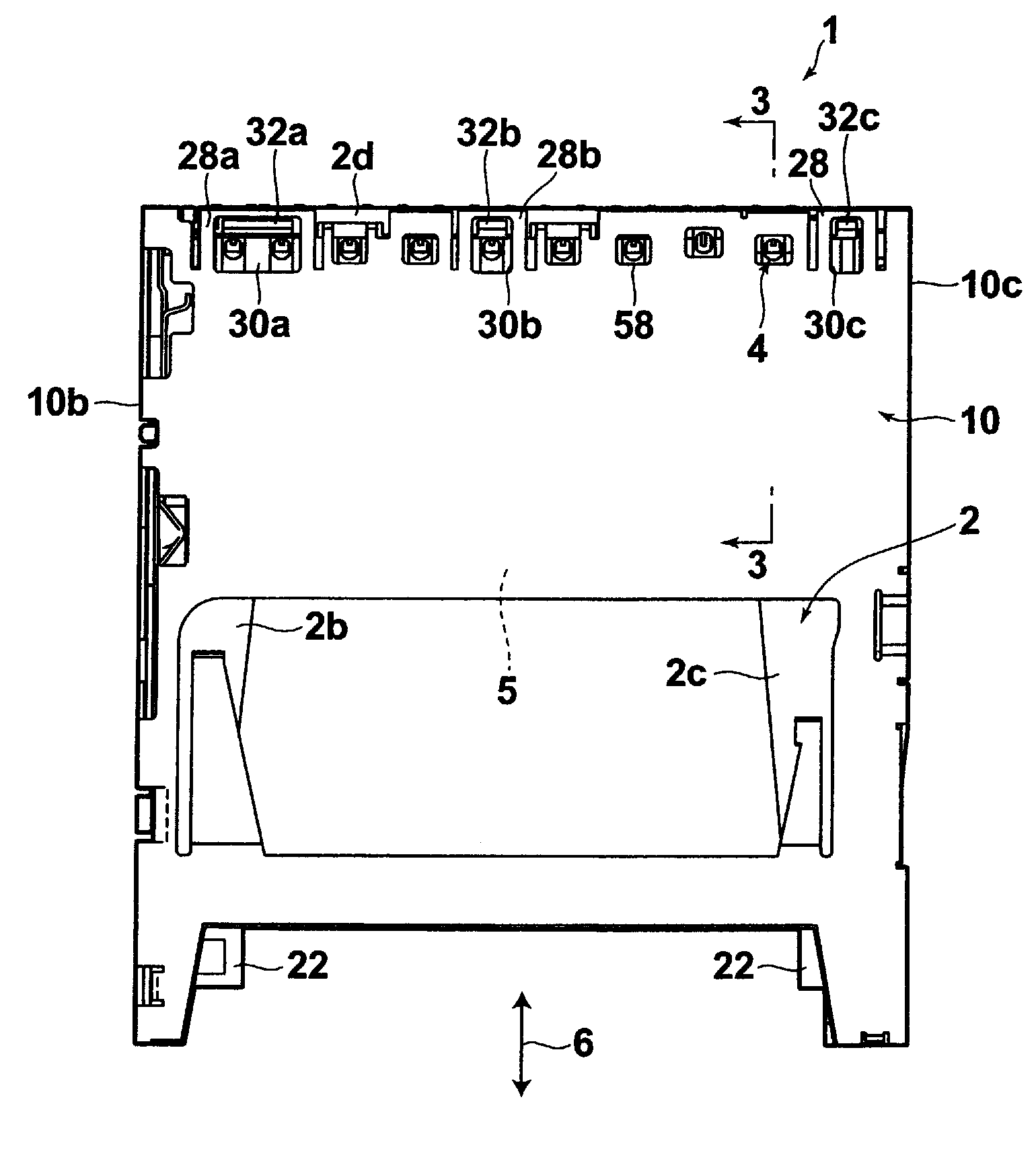
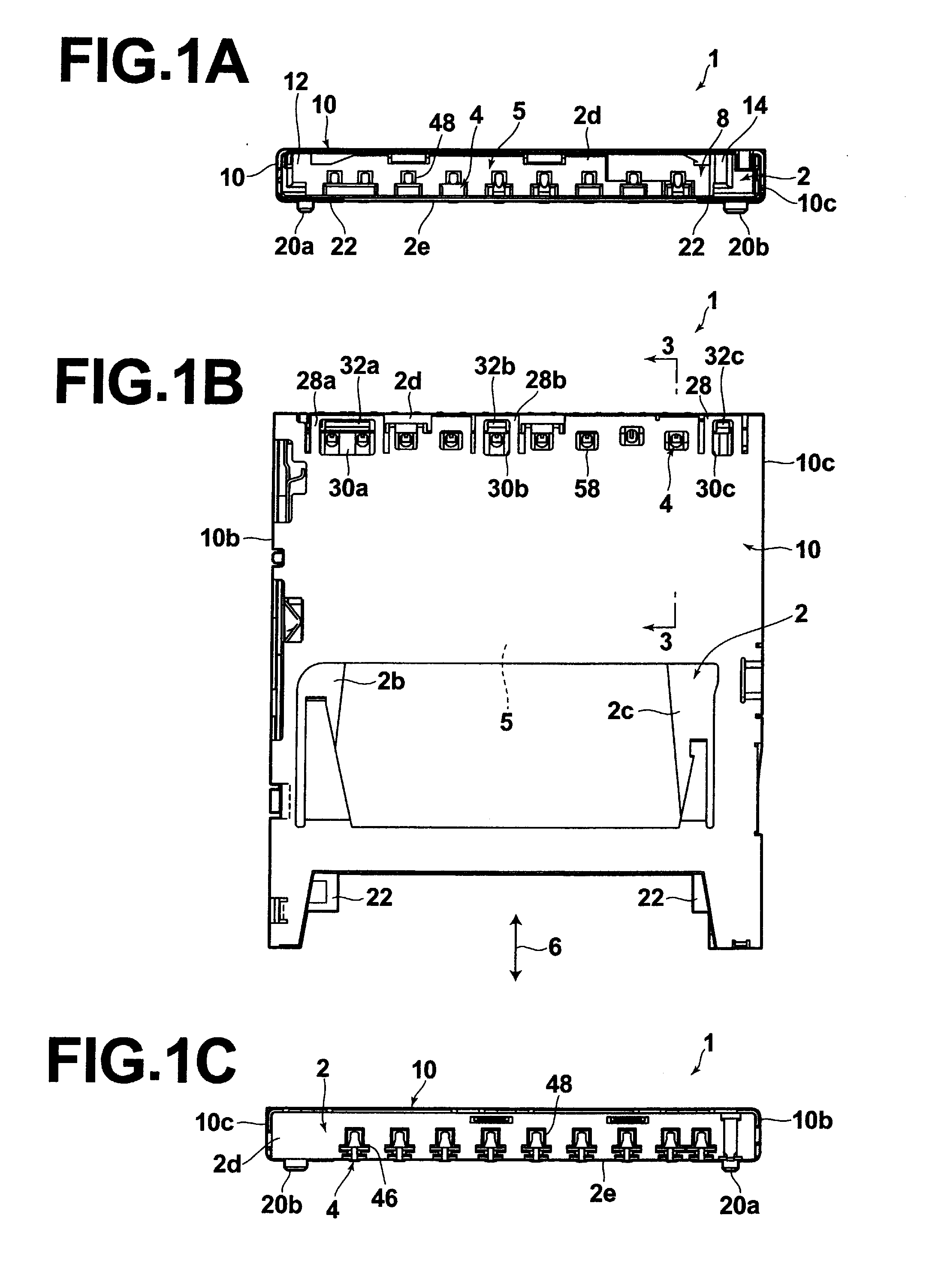
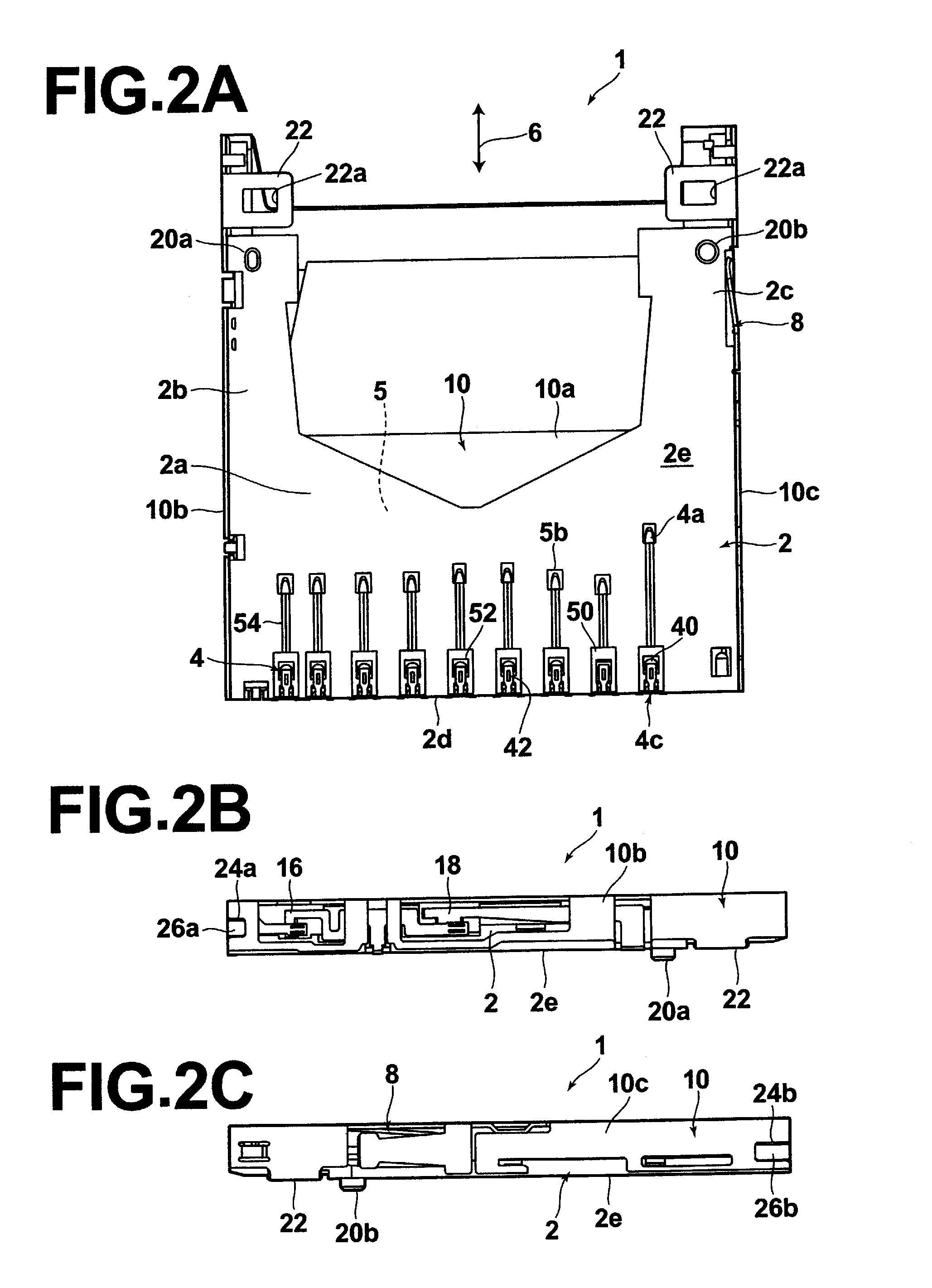
[0022]Hereinafter, an exemplary embodiment of a surface mount electrical connector (hereinafter, simply referred to as “connector”), of the present invention will be described with reference to the accompanying drawings. First, an overview of the connector 1 will be described with reference to FIGS. 1A to 2C. FIGS. 1A to 1C and FIGS. 2A to 2C illustrate overviews of the connector 1, in which FIG. 1A is a front view, FIG. 1B is a plan view, FIG. 1C is a rear view, FIG. 2A is a bottom view, FIG. 2B is a left side view, and FIG. 2C is a right side view. In the following description, the referent of “front” means a side from where a card (not shown) is inserted, and “rear” means a side opposite to the front in the plan view of the connector 1 in FIG. 1B. The connector 1 is a card connector and comprises a housing 2, contacts 4 held by the housing 2, an ejection mechanism 8, and a metal shell 10 attached to the housing and substantially covers these components. The ejection mechanism 8 i...


PUM


Abstract

A surface mount electrical connector for mounting to a substrate comprising a housing and a contact carried by the housing, the contact comprising a retention section held by the housing and a tine configured for mounting to a surface of the substrate wherein the tine extends from the retention section and wherein the tine lies inside an outer contour line of the housing is disclosed. A method of connecting a surface mount electrical connector to a substrate comprising the steps of providing a housing carrying a contact, the contact having a tine within a projected footprint of the housing on the substrate, attaching the housing to the substrate, inserting a jig into an opening of the housing, and bending the tine toward the substrate is disclosed.

Description

TECHNICAL FIELD [0001]The present invention relates to an electrical connector, and more specifically, to a surface mount electrical connector in which tines of electrical contacts held by the electrical connector are surface mounted on a circuit board.BACKGROUND ART [0002]Various types of surface mount electrical connectors are known. As an example, a memory card connector device that comprises a contact block, having contacts held therein, provided in the rear portion of the connector body, and a slider that moves within the connector body in the forward-backward directions according to an insertion / removal operation of a card is known as described, for example, in Japanese Unexamined Patent Publication No. 2004-207168 (FIGS. 5, 6). The contact block used in the connector device comprises a heart cam groove, which collaborates with a lock metal that moves therein to form what is known as the push-push connector. In the connector device, the tines of the contacts are protruding ext...

Claims


Application Information

Patent Timeline
Patent Type & Authority Applications(United States)
IPC IPC(8): H01R12/00
CPCH01R12/57H01R12/716H01R43/0263H01R43/0249H01R13/2442H01R12/71H01R12/73
Inventor TSUJI, JUNYA
Owner TYCO ELECTRONICS JAPAN GK
Why Eureka
Try Eureka