Multi-stage driving circuit

A driving circuit and driving signal technology, which is applied in the direction of instruments and static indicators, etc., can solve the problem of excessive occupied area, achieve the effect of reducing the area of ​​the circuit board and saving the occupation of the panel frame

Pending Publication Date: 2020-02-07
FUJIAN HUAJIACAI CO LTD
View PDF0 Cites 0 Cited by
  • Summary
  • Abstract
  • Description
  • Claims
  • Application Information

AI Technical Summary

Problems solved by technology

[0004] For this reason, it is necessary to provide a new panel drive circui

Method used


Image

  • Multi-stage driving circuit
  • Multi-stage driving circuit
  • Multi-stage driving circuit

Examples


Example Embodiment

[0022] In order to describe in detail the technical content, structural features, achieved objectives and effects of the technical solution, the following detailed descriptions are given in conjunction with specific embodiments and accompanying drawings.
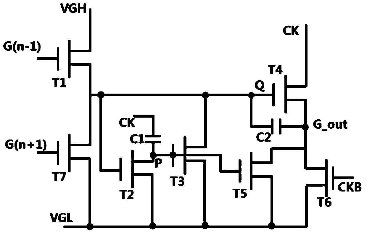
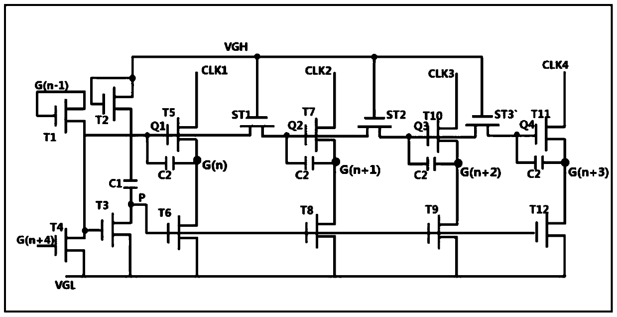
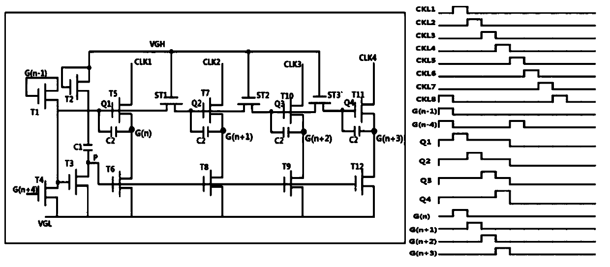
[0023] In some specific embodiments, GIP circuits are generally designed to be distributed on both sides of the display area (Active Area), such as figure 1 The 7T2C-GIP driving circuit shown is a single-stage output (G_out in the figure). In addition, the 4 clock signals of the GIP circuit unit correspond to 4 output signals. This kind of GIP circuit wants to output G(n), G(n+1), G(n+2), G(n+3) 4-level output Signal, you need 28 TFTs and 8 capacitors, we are figure 2 In the illustrated embodiment, a new type of circuit is proposed. Under the same function of generating 4-level gate signals, the number of TFTs is 15, which is 13 fewer than the number of TFTs in the existing GIP circuit. The reduction in the number of TFTs can ...


PUM


Abstract

The invention discloses a multi-stage driving circuit. The multi-stage driving circuit comprises thin film transistors T1, T2, T3, T4, T5, T6, T7, T8, T9, T10, T11, T12, ST1, ST2 and ST3. The source electrode and the grid electrode of the T1 are connected with an upper-stage driving signal; the drain electrode of the T1 is connected with the source electrode of the T4; the grid electrode of the T4is connected with a latter four-stage driving signal; the drain electrode of the T1 is further connected with the grid electrode of the T3 and the grid electrode of the T5; the source electrode of the T3 is connected with the drain electrode of the T2 through the first capacitor; the source electrode of the T3 is further connected with the drain electrodes of the T6, T8, T9 and T12; the drain electrode of the T5 is connected with a current-stage scanning signal, and the source electrode of the T5 is connected with a first clock signal; the grid electrode of the T5 is further connected with the drain electrode of the T5 through a second capacitor, and the source electrode of the T6 is connected with the drain electrode of the T5. According to the technical scheme, the four clock signals can be received and correspond to the four output signals at the same time, that is, the driving signals of the current stage, the later stage, the later second stage and the later third stage are output, the number of TFTs is reduced in architecture, finally, the needed circuit board area is reduced, and therefore panel frame occupation is reduced.

Description

technical field [0001] The invention relates to panel driving technology, in particular to the design of a new driving circuit capable of reducing the border. Background technique [0002] GIP technology (Gate Driver In Panel): array gate drive technology, widely used in liquid crystal display panels (LCD) and AMOLED display panels. GOA technology is to manufacture the driving circuit of the horizontal scanning line on the substrate around the display area (ActiveArea), so that it can replace the external integrated circuit board (Integrated Circuit, IC) to complete the driving of the horizontal scanning line. GIP technology can reduce external The welding (bonding) process of the IC reduces the production cost. At present, the panel design mostly adopts bilateral GIP drive to achieve narrow frame, but the traditional GIP circuit structure is complex and almost all single-stage G_out output, and as the frame gets smaller The closer the distance between the sealant and the a...

Claims


Application Information

Patent Timeline
IPC IPC(8): G09G3/20
CPCG09G3/20
Inventor 卢昭阳罗敬凯
Owner FUJIAN HUAJIACAI CO LTD
Why Eureka
Try Eureka