Upright composite common mode coil assembly

a common-mode coil and composite technology, applied in the direction of transformer/react mounting/support/suspension, transformer/inductance magnetic core, inductance, etc., can solve the problem of leaking inductance formed in the bobbin carrier, the area of the circuit board cannot be effectively reduced, and the air cannot be easily circulated, etc., to achieve the effect of facilitating automatic discharging

Active Publication Date: 2019-10-29
YUJING TECH CO LTD
View PDF3 Cites 0 Cited by
  • Summary
  • Abstract
  • Description
  • Claims
  • Application Information

AI Technical Summary

Benefits of technology

[0007]One main objective of the present invention is to provide an upright composite common mode coil assembly that facilitates automatic discharging on a production line.
[0008]Another objective of the present invention is to provide an upright composite common mode coil assembly that reduces the layout area of a circuit board on which the assembly is provided.
[0010]Yet another objective of the present invention is to provide an upright composite common mode coil assembly that increases heat dissipation efficiency by increasing air circulation.
[0011]Yet another objective of the present invention is to provide an upright composite common mode coil assembly that facilitates stacking of a plurality of these assemblies.
[0013]As such, one bobbin of the coil carrier is received in each of the receiving slots of the seat, and wires of a group of coils are guided into some of the recessed portions through the wire slots and the indentations, and wires of another group of the coils are guided into the other recessed portions through the notches, so that the wires of the coils do not protrude out of the seat and can be neatly soldered on the pins. Meanwhile, such an assembly facilitates automatic discharging in the production line, reduces layout area of a circuit board on which the assembly is provided, and facilitates stacking of a plurality of these assemblies.
[0019]According to the above structure, the wing portions of the indentations near the bottom portion overlie the surfaces of the wires, such that after the wires are passed into the recessed portions, the concaved portions facilitate neat soldering of the wires on the pins.

Problems solved by technology

A current is passed through the plurality of coils in each bobbin, resulting in a leakage inductance formed in the bobbin carrier.
However, the coils in this publication are arranged side by side horizontally, so they will occupy a large area on a circuit board when they are actually connected to the circuit board, and as a result of this, the area of the circuit board cannot effectively reduced.
Meanwhile, when the coils are in operation, they will produce heat, but due to the horizontal arrangement of the coils, the coil are in proximity to the circuit board, which will not allow air to circulate easily.
The poor heat dissipation leads to higher temperature and lower efficiency.
The poor heat dissipation leads to higher temperature and lower efficiency or even a burnt device.

Method used


Image

  • Upright composite common mode coil assembly
  • Upright composite common mode coil assembly
  • Upright composite common mode coil assembly

Examples


Embodiment Construction

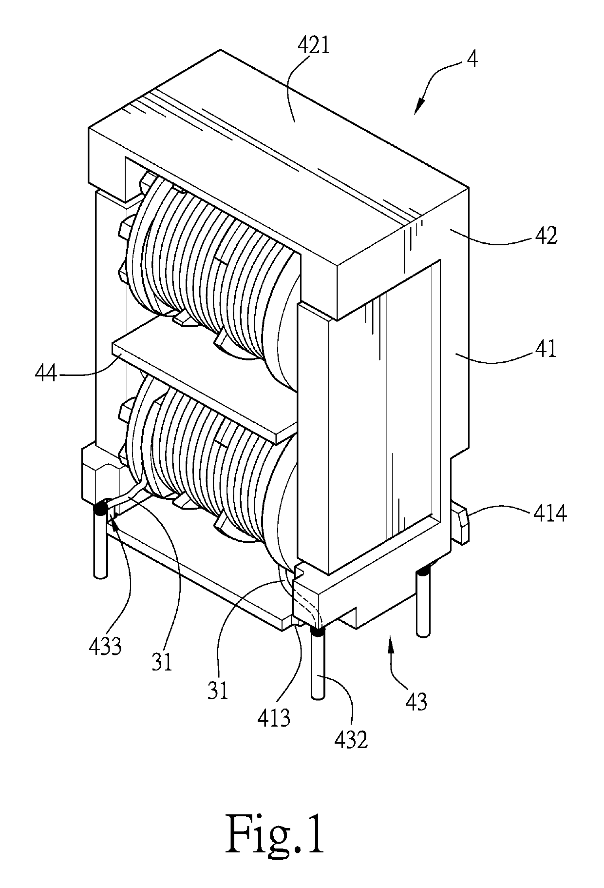
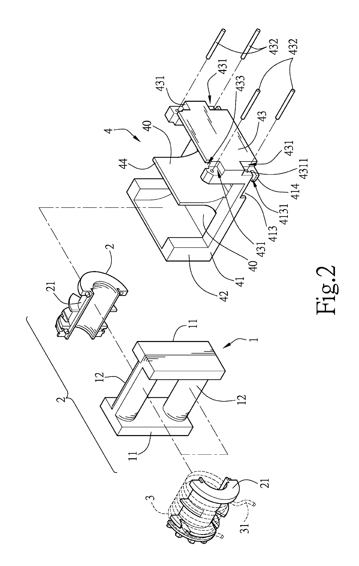
[0026]With reference to FIGS. 1 to 4, the structure of an upright composite common mode coil assembly in accordance with the present invention mainly includes a coil carrier 1 and a seat 4, wherein the coil carrier 1 includes two carrier plates 11 and two bobbins 2. The two carrier plates 11 are connected through two columns 12. Each of the bobbins 2 includes two semi-bobbins 21, and the two semi-bobbins 21 combine to surround one of the two columns 12. A plurality of coils 3 are wound around the outer circumference of each of the bobbins 2.

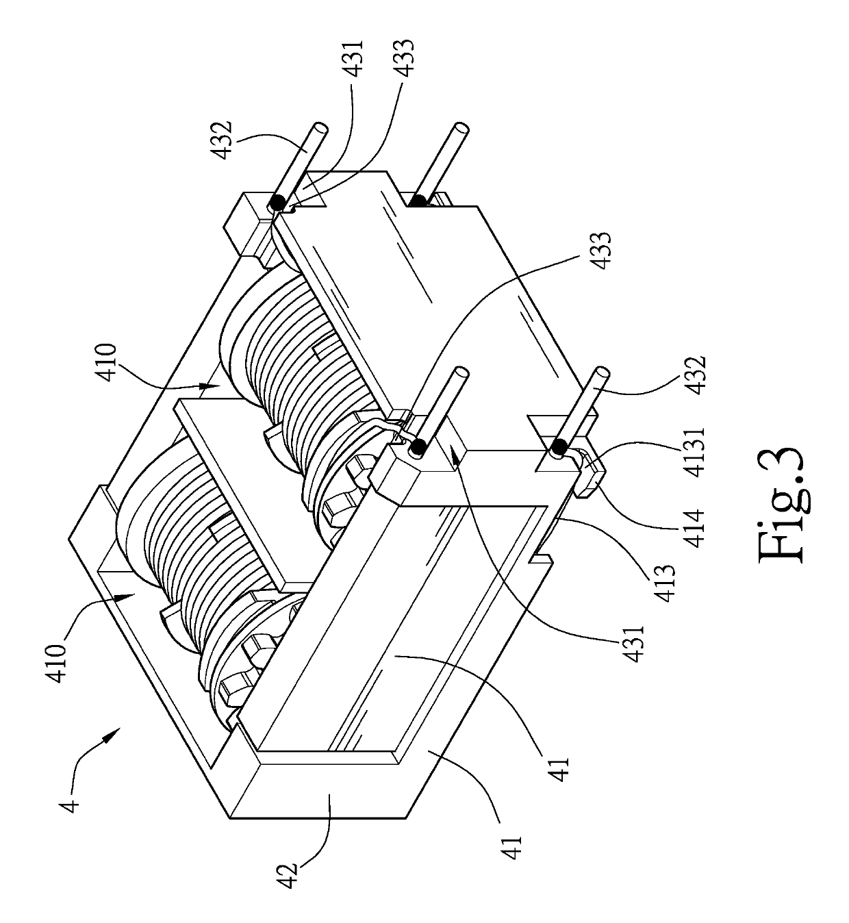
[0027]The seat 4 includes a base 41, a bottom portion 43, a top portion 42 and a separating portion 44, wherein a surface of the base 41 includes a back plate 411. Hollow portions 410 are formed at an upper position and a lower position of the back plate 411. A wire slot 412 is formed at either side of the back plate 411. An indentation 413 extends from one end of each of the wire slots 412. A wing portion 414 extends from a side of the indentati...


PUM

PropertyMeasurementUnit
outer circumferenceaaaaaaaaaa
DC voltageaaaaaaaaaa
leakage inductanceaaaaaaaaaa

Abstract

An upright composite common mode coil assembly includes a coil carrier and a seat. The coil carries includes two bobbins with a plurality of coils wounded thereon. The seat includes a base, a bottom portion, a top portion and a separating portion. The base has a back plate on a surface thereof, hollow portions formed at an upper position and a lower position thereof, a wire slot and an indentation are provided at either side of the back plate. The bottom portion and the top portion extend vertically from two sides of the base. A recessed portion is formed at each of the corners of the bottom portion, and a pin is inserted into each of the recessed portions. The top portion has a flat top face. The separating portion extends from another surface of the base and tapered to form a curved surface, and form two receiving slots with the top portion and the bottom portion, respectively. Each of the bobbins of the coil carrier is received in one of the receiving slots of the seat, and wires of a group of the coils are guided into some of the recessed portions through the wire slots and the indentations, and wires of another group of the coils are guided into the other recessed portions through the notches, so that the wires of the coils do not protrude out of the seat and are neatly soldered on the pins.

Description

BACKGROUND OF THE INVENTION[0001]1. Field of the Invention[0002]The invention relates to an upright composite common mode coil assembly that facilitates automatic discharging on a production line, reduces the layout area of a circuit board, and facilitates stacking of a plurality of these assemblies; the assembly also has no protruding wires.[0003]2. Description of the Prior Art[0004]Conventionally, a transformer having a common mode choke and a differential mode choke, in operation, receives an AC voltage source, which is passed through the common mode choke and the differential mode choke to a rectifier, and a DC voltage source is outputted. The common mode choke and the differential choke are used to cancel common mode noise and differential mode noise. A reference is made here to a TW Patent Publication No. I341540, titled “Composite Common Mode Coil”, which includes: a base, a coil carrier, and an iron core. The base has two receiving slots and a separating slot located between...

Claims


Application Information

Patent Timeline
Patent Type & Authority Patents(United States)
IPC IPC(8): H01F27/28H01F27/26H01F37/00H01F27/06H01F27/30H01F5/04H01F27/32H01F27/02H01F17/00H01F41/00
CPCH01F27/06H01F37/00H01F27/02H01F5/04H01F27/266H01F27/306H01F27/325H01F2005/046H01F2017/0093H01F41/00H01F2027/065H01F27/292
Inventor YANG, SEN-TAI
Owner YUJING TECH CO LTD
Why Eureka
Try Eureka