Medical injection system

a technology of injection system and injection tube, which is applied in the field of medical injection system, can solve the problems of mainly unnecessary surgery and achieve the effect of facilitating manufacturing and avoiding significant downtim

Active Publication Date: 2009-03-19
ACIST MEDICAL SYST
View PDF51 Cites 51 Cited by
  • Summary
  • Abstract
  • Description
  • Claims
  • Application Information

AI Technical Summary

Benefits of technology

[0011]In one aspect of the present invention, there is a method of injecting a contrast agent that minimizes the extravasation of the agent. The method involves the use of a preliminary injection of an easily absorbable liquid, such as saline, to establish the absence of extravasation.

Problems solved by technology

Thus, if extravasation occurs while injecting saline, a fasciotomy is typically unnecessary.

Method used


Image

  • Medical injection system
  • Medical injection system
  • Medical injection system

Examples


Embodiment Construction

Method of Preventing Extravasation

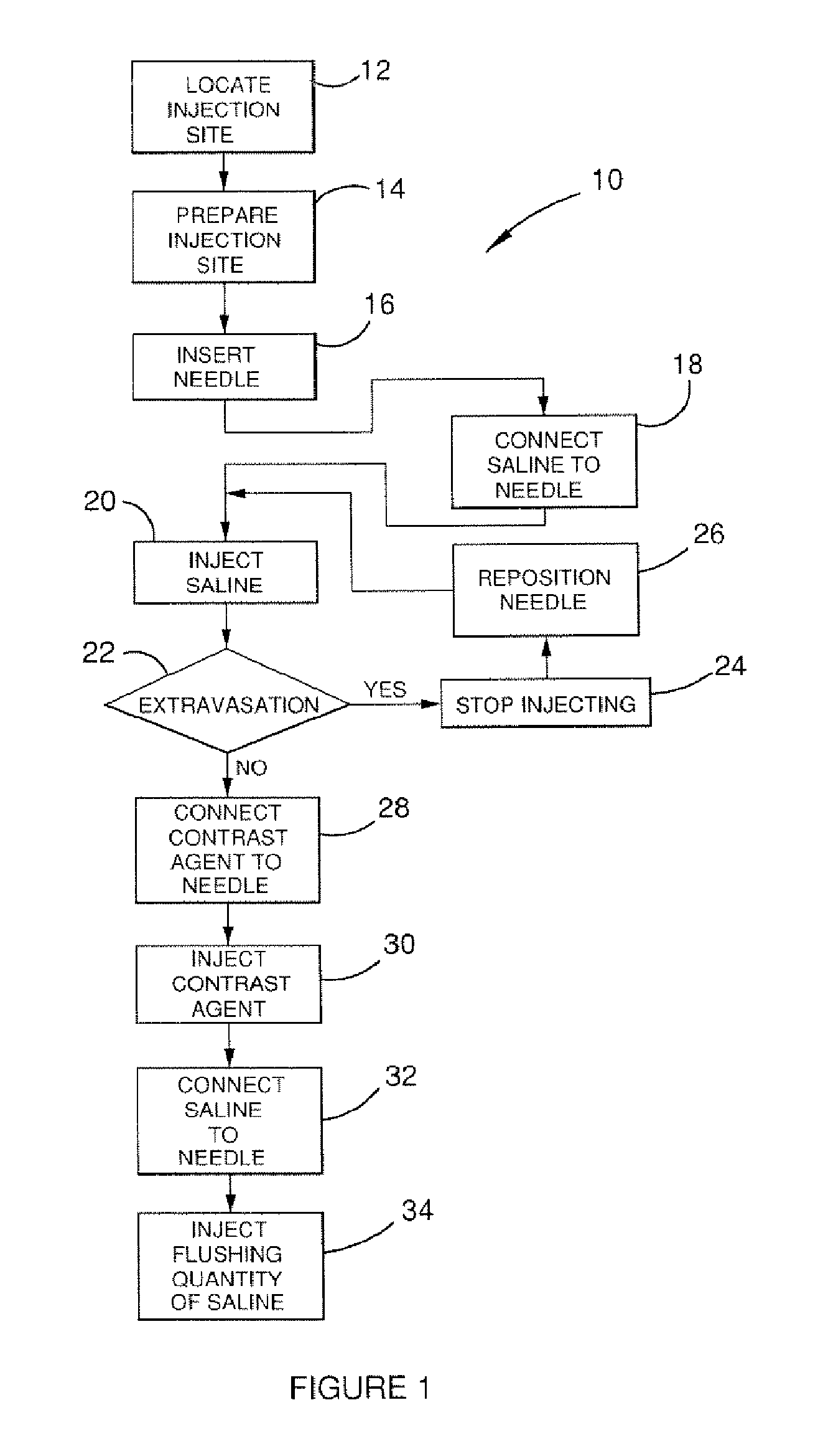
[0057]FIG. 1 shows a flow diagram of the method of preventing extravasation 10 of the present invention. Beginning at 12, an injection site is located by the attending health professional and prepared for injection at 14 using appropriate cleaning techniques. The needle or catheter is inserted at 16 to establish fluid communication between the needle or catheter and the targeted lumen of the patient.

[0058]At 18, a supply of saline is fluidly connected to the needle or catheter and, at 20, a quantity of saline is injected into the patient at a predetermined flow rate that may be approximately equal to the desired flow rate of the eventual contrast agent injection. It is preferred that the flow rate of the saline injection be at least as great as the planned flow rate of the contrast agent. Doing so ensures that extravasation complications caused by jetting forces will be revealed prior to the introduction of the contrast agent. While the saline is be...


PUM


Abstract

A method of preventing extravasation of contrast agent during a computed tomography injection. An automatic injector device facilitates ease of accomplishing the method. The method includes establishing the absence of extravasation using an absorbable injectate, such as saline, prior to injecting the contrast agent. The device includes a computerized injector head capable of switching between two injectates without physical human intervention. The device is controlled by a remote operating panel located in a control room that is protected from X-ray radiation. The device includes various software driven safety features that prevent the occurrence of unsafe conditions.

Description

CROSS REFERENCE TO RELATED APPLICATIONS[0001]This application is a divisional of U.S. application Ser. No. 10 / 126,799, filed on Apr. 19, 2002, which claims priority from U.S. Provisional Application Ser. No. 60 / 294,471 filed on May 30, 2001, all of which are incorporated by reference herein in their entirety.BACKGROUND OF THE INVENTION[0002]Computed tomography (hereinafter “CT”) is a medical procedure whereby an X-ray imaging machine is used to take cross-sectional images of a patient. The source of the X-rays is placed on one side of the body while an array of detectors is placed on the other side. The X-rays pass through the body and are read by the detectors on the other side. The signals received by the detectors are sent to a computer which compiles the data to create images. The detectors and X-ray source may be rotated around the body, while the body is being translated axially, to create a plurality of layered images.[0003]CT differs from traditional X-ray imaging in that a ...

Claims


Application Information

Patent Timeline
Patent Type & Authority Applications(United States)
IPC IPC(8): A61M37/00A61M5/00A61M5/145A61M5/19A61M5/31A61M5/315
CPCA61M5/007A61M5/14546A61M5/14566A61M2005/3128A61M5/31513A61M5/31515A61M5/19
Inventor TOEWS, GLENNSZCZECH, CHRISMCPEAK, THOMAS J.DUCHON, DOUGLAS J.
Owner ACIST MEDICAL SYST
Why Eureka
Try Eureka