Prop

a technology for props and prop legs, applied in the field of props, can solve the problems of reducing the application range of props, affecting the quality of construction equipment, and taking a long time to complete, and achieve the effect of quick adjustment in length

Inactive Publication Date: 2009-04-23
SHIH LUNG CHING
View PDF24 Cites 22 Cited by
  • Summary
  • Abstract
  • Description
  • Claims
  • Application Information

AI Technical Summary

Benefits of technology

[0007]It is therefore a primary object of the present invention to provide a prop which can be quickly adjusted in length.
[0008]It is a further object of the present invention to provide the above prop which is able to bear both axial pressure and tension. Therefore, the application range of the prop is widened.

Problems solved by technology

First, the length of the prop is adjusted by means of turning the locating nut 17. It takes much time to complete such procedure. Therefore, a user can hardly quickly conveniently adjust the length of the prop to a necessary length.
Second, such prop 10 is designed for bearing pressure only. Therefore, the prop 10 cannot bear pulling force. In the case that an axial pressure is applied to the prop 10, the inner tube 15 is supported by the nut 17 without being retracted into the outer tube 12. However, in the case that an axial pulling force is applied to the prop, the inner tube will slide and displace. Accordingly, the prop can only bear one-way action force, that is, the axial pressure. Therefore, such prop is inapplicable to the situation of bidirectional action force so that the application range of such prop is narrowed.
However, it is relatively inconvenient to operate such prop.
In addition, the prop has a relatively complicated structure.

Method used


Image

  • Prop
  • Prop
  • Prop

Examples


Embodiment Construction

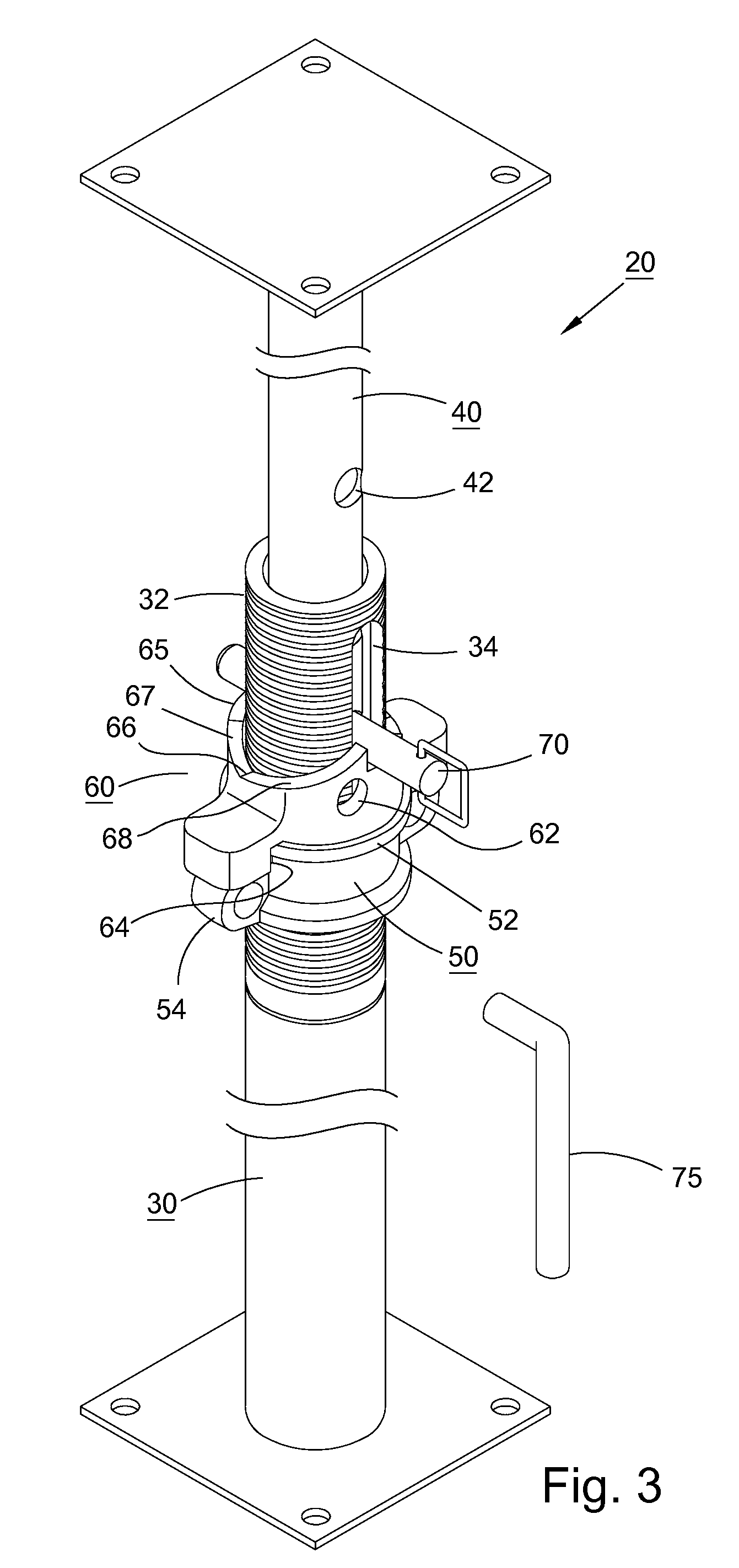
[0021]Please refer to FIGS. 3 and 4. According to a first embodiment, the prop 20 of the present invention includes an outer tube 30, an inner tube 40, a locating nut 50, an insertion pin 70 and a controlling member 60.

[0022]A top end of the outer tube 30 is a threaded section 32 with a thread formed on outer circumference of the threaded section. The threaded section and the outer tube 30 can be a one-piece member or two pieces fixedly connected with each other. A pair of slots 34 is axially formed on the threaded section 32 of the outer tube 30.

[0023]The inner tube 40 is telescopically fitted in the outer tube 30. The inner tube 40 is formed with several pairs of pinholes 42 axially arranged at equal intervals.

[0024]The locating nut 50 is screwed on the threaded section 32 of the outer tube 30. By means of turning the nut 50, the height of the nut 50 on the threaded section 32 can be adjusted. An annular rib 52 is formed on outer circumference of the nut 50. Preferably, the annula...


PUM


Abstract

A prop for construction. The prop includes an outer tube and an inner tube telescopically fitted in the outer tube. The top end of the outer tube has a threaded section axially formed with a pair of slots. The inner tube is axially formed with several pairs of pinholes. A locating nut is screwed on the threaded section of the outer tube. A controlling member formed with a pair of through holes is fitted on the outer tube. A bottom end of the controlling member is rotatably connected with the locating nut. A top face of the controlling member is formed with recessed / projecting structures. An insertion pin is fitted through the slots of the outer tube and inserted in one pair of pinholes of the inner tube, and is rested on the top face of the controlling member, whereby the prop can support a horizontal moldboard. By means of turning the controlling member, the insertion pin and the inner tube can be quickly lowered to separate the top end of the prop from the moldboard. Alternatively, the insertion pin can be fitted through the through holes of the controlling member, the slots of the outer tube and inserted in one pair of pinholes of the inner tube, whereby the prop is able to bear both axial pressure and tension.

Description

FIELD OF THE INVENTION[0001]The present invention is related to a construction equipment, and more particularly to a prop.BACKGROUND OF THE INVENTION[0002]FIGS. 1 and 2 show a conventional prop 10 for supporting moldboards. The prop 10 includes an outer tube 12, a threaded tube 13 fixed at a top end of the outer tube 12 and an inner tube 15 telescopically fitted in the threaded tube 13 and the outer tube 12. The threaded tube 13 is formed with a pair of axial slots 14. The inner tube 15 is formed with several pairs of pinholes 16 arranged at equal intervals. A locating nut 17 is adjustably screwed on the threaded tube 13. An insertion pin 18 is passed through the slots 14 of the threaded tube 13 and inserted into one pair of pinholes of the inner tube 15. In use, the inner and outer tubes 15, 12 are adjusted to a necessary length and then the insertion pin 18 is inserted through the slots 14 of the threaded tube 13 into one pair pinholes 16 of the inner tube 15. The insertion pin 18...

Claims


Application Information

Patent Timeline
Patent Type & Authority Applications(United States)
IPC IPC(8): E04G25/06
CPCE04G17/14E04G25/06E04G21/26E04G25/068E04G25/061E04G25/065E04G25/063E04G2025/006
Inventor SHIH, LUNG CHING
Owner SHIH LUNG CHING
Why Eureka
Try Eureka