Powering cell phones and similar devices using RF energy harvesting

a cell phone and energy harvesting technology, applied in the direction of antenna details, support structure mounting, antennas, etc., can solve the problems of unsatisfactory lifetime cost and maintenance requirements of applications, unscheduled maintenance trips are even more costly and disruptive, and many devices do not provide the lifetime cost and maintenance requirements for applications

Inactive Publication Date: 2009-04-23
POWERCAST
View PDF13 Cites 572 Cited by
  • Summary
  • Abstract
  • Description
  • Claims
  • Application Information

AI Technical Summary

Benefits of technology

[0011]Traditional RF receiving devices have focused on maximizing selectivity of the frequency to isolate and to be coherent without interference from other sources. In contrast, while this methodology operates at a specific frequency or range of frequencies, the device accepts any interference to supplement the output power of the device. Also, the research related to power harvesting that uses RF energy as a source has primarily focused on devices in close proximity of the source. In most cases, prior research assumed a dedicated or directed source of RF to power the device.
[0019]With this method and apparatus a device's power storage components do not require replacement, thus enabling the device to be permanently placed off-grid, where it may be physically impractical, costly, or dangerous (due to a harsh environment) to provide maintenance.

Problems solved by technology

Even with power conscious designs and the latest in battery technology, many devices do not provide the lifetime cost and maintenance requirements for applications that require a large number of untethered devices such as logistics, and building automation.
For both device types, scheduled power-source maintenance is costly and disruptive to the entire system that a device is intended to monitor and / or control.
Unscheduled maintenance trips are even more costly and disruptive.
On a macro level, the relatively high cost associated with the internal battery also reduces the practical, or economically viable, number of devices that can be deployed.

Method used


Image

  • Powering cell phones and similar devices using RF energy harvesting
  • Powering cell phones and similar devices using RF energy harvesting
  • Powering cell phones and similar devices using RF energy harvesting

Examples


Embodiment Construction

[0124]A complete understanding of the invention will be obtained from the following description when taken in connection with the accompanying drawing figures wherein like reference characters identify like parts throughout.

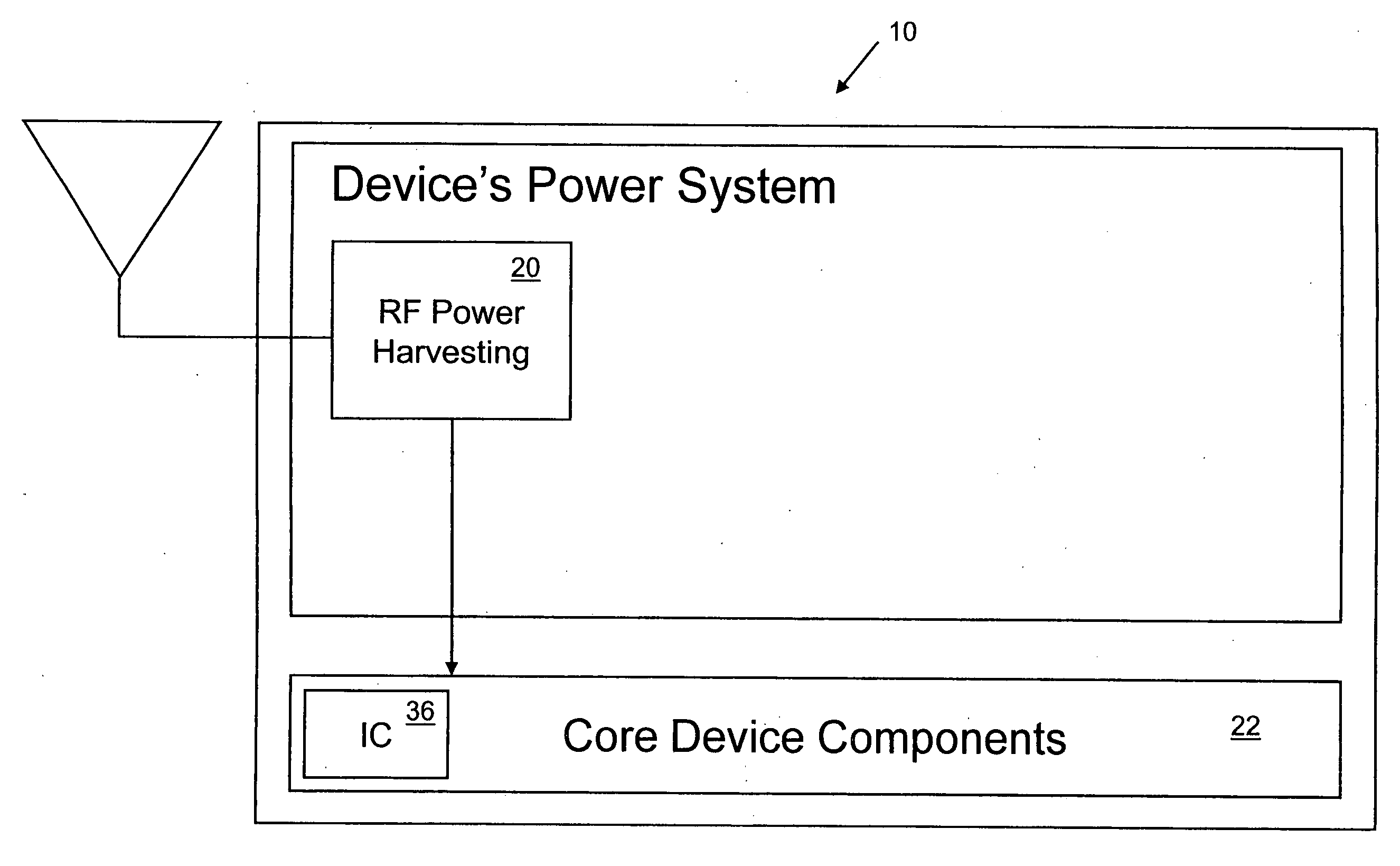
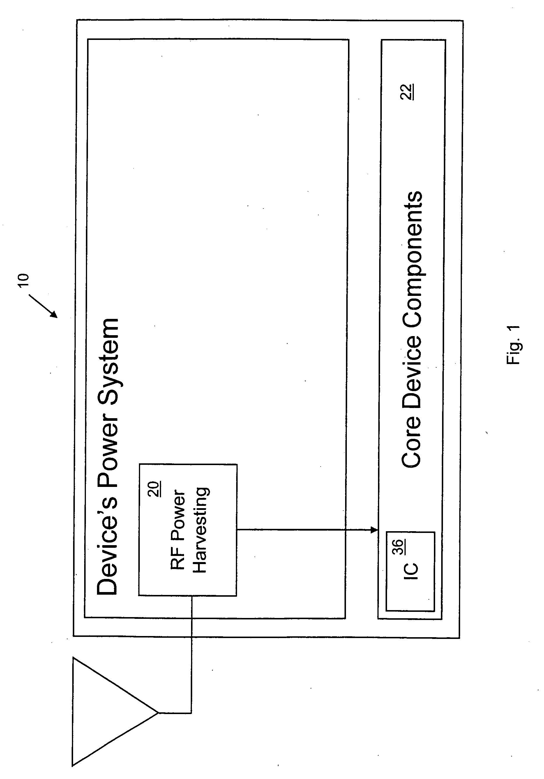
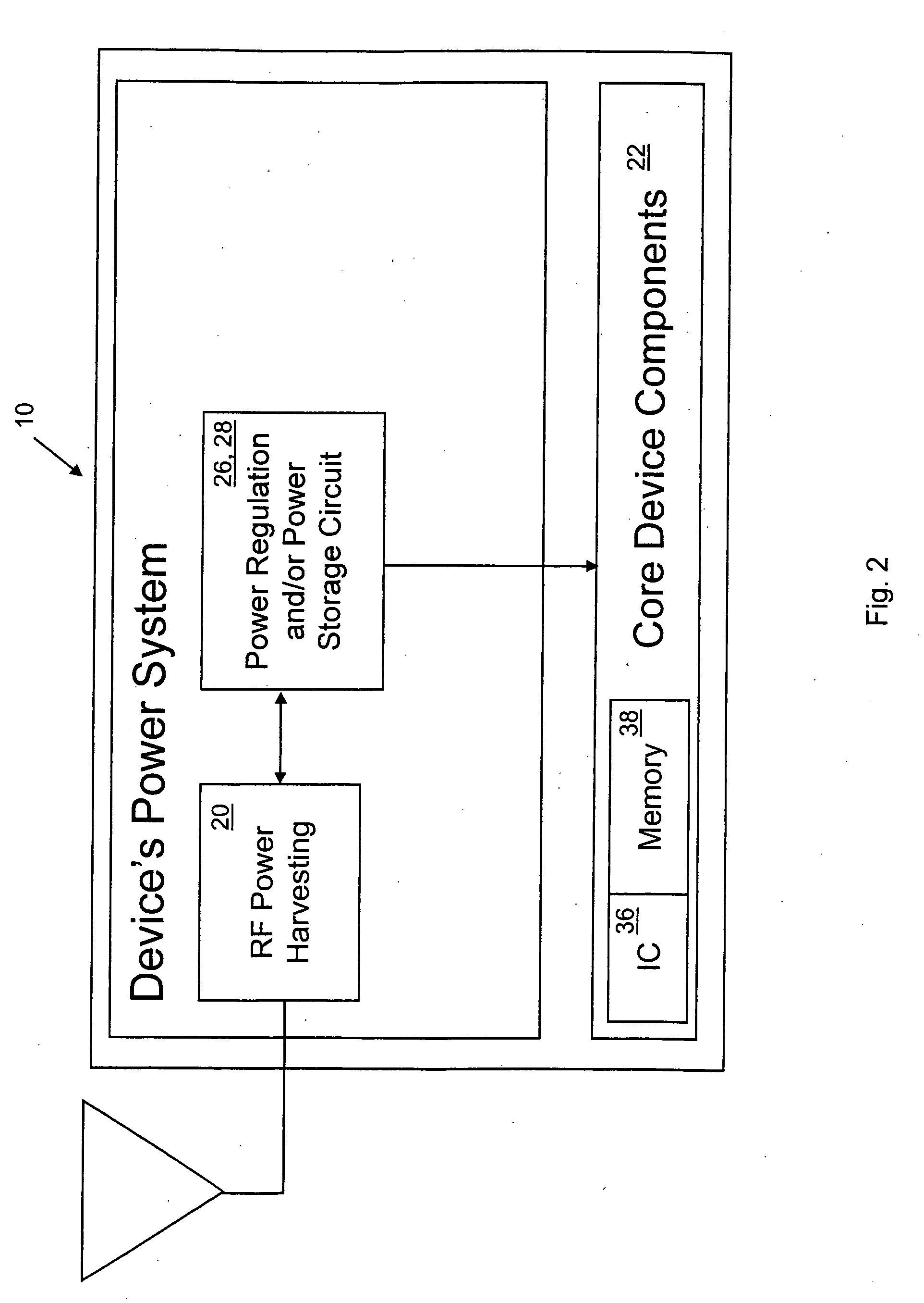
[0125]There is shown an apparatus 10 for an application. The apparatus 10 comprises a core device 22 preferably having an integrated circuit for the application. The apparatus 10 comprises a power harvester 20 connected to the core device 22 to power the core device 22.

[0126]The apparatus 10 preferably includes an alternative power source 24 connected to the core device 22 to power the core device 22 in conjunction with the power harvester 20. Preferably, the apparatus 10 includes a power regulator 26 and / or power storage circuit 28 connected to the power harvester 20. The apparatus 10 preferably includes a power storage charger 30 connected to the power harvester 20. Preferably, the apparatus 10 includes a power storage connected to the power harvester 20.

[0127]...


PUM


Abstract

A device for receiving wireless power includes a point of reception, wherein the point of reception is positionable in at least a first position and a second position. A method for receiving wireless power. The method includes the steps of positioning a point of reception in contact with a housing to a first position. There is the step of receiving wireless power at the point of reception and providing it to a power harvester in the housing. There is the step of converting the wireless power to usable DC with the power harvester. There is the step of providing the usable DC to core components in the housing. There is the step of using the DC by the core components. There is the step of repositioning the point of reception to a second position. There is the step of receiving wireless power at the point of reception at the second position and providing it to the power harvester. There is the step of converting the wireless power received by the point of reception in the second position to usable DC with the power harvester. There is the step of providing the usable DC to the core components in the housing. There is the step of using the DC by the core components.

Description

FIELD OF THE INVENTION[0001]The present invention is related to the wireless powering of devices. More specifically, the present invention is related to the wireless powering of devices, namely cell phones and the like, with a power harvester.BACKGROUND OF THE INVENTION[0002]As processor capabilities have expanded and power requirements have decreased there has been an ongoing explosion of devices that operate completely independent of wires or power cords. These “untethered” devices range from cell phones, and wireless keyboards to building sensors and active RFID tags.[0003]Engineers and designers of these untethered devices continue to have to deal with the limitations of portable power sources, primarily batteries as the key design parameter. While performance of processors and portable devices have been doubling every 18-24 months driven by Moore's law, battery technology in terms of capacity has only been growing at measly 6% per year. Even with power conscious designs and the...

Claims


Application Information

Patent Timeline
Patent Type & Authority Applications(United States)
IPC IPC(8): H02J17/00
CPCH01Q1/248H01Q1/243
Inventor GREENE, CHARLES E.HARRIST, DANIEL W.MCELHINNY, MICHAEL THOMAS
Owner POWERCAST
Why Eureka
Try Eureka