
Non-contact selection device

Active Publication Date: 2009-04-30
MILA CO LTD
View PDF1 Cites 50 Cited by
  • Summary
  • Abstract
  • Description
  • Claims
  • Application Information

AI Technical Summary

Benefits of technology

[0010]Accordingly, the present invention provides a device and method capable of non-contactly selecting a function that can allow a user to more easily and quickly select a function by remote-controlling a menu function by use of a camera.
[0012]The prevent invention provides a device and method capable of non-contactly selecting a function that can maximize making the most use of elements by allowing an equipped camera to be universally used.
[0013]The prevent invention provides a device and method capable of non-contactly selecting a function that can reduce a manufacturing cost for a key pad and make its size minimized and its design varied by making the best use of the internal space of a digital device.
[0015]The prevent invention provides a device and method capable of non-contactly selecting a function that can not only reduce a manufacturing cost of a digital device by removing a key pad but also make its size minimized and its design varied by making the best use of the internal space of the digital device.
[0083]It can be predetermined that the moving width, displayed on a display unit of the digital processing device, is increased or decreased by the increasing or the decreasing of the area.
[0092]It can be predetermined that the moving width, displayed on a display unit of the digital processing device, is increased or decreased by the increasing or the decreasing of the area.

Problems solved by technology

Particularly, although limited functions are actually used as compared with enormous functions of today's digital devices, it is a troublesome work for the user to have to undergo the aforementioned complicated operation, in order to select a desired function.
Accordingly, this additional molding operation causes to make its manufacturing process complicated and to increase its manufacturing unit price.
However, this method also leads to the increase of its manufacturing cost due to the equipment of a display unit capable of the touch screen.

Method used


Image

  • Non-contact selection device
  • Non-contact selection device
  • Non-contact selection device

Examples


Embodiment Construction

[0126]The above objects, features and advantages will become more apparent through the below description with reference to the accompanying drawings.

[0127]Since there can be a variety of permutations and embodiments of the present invention, certain embodiments will be illustrated and described with reference to the accompanying drawings. This, however, is by no means to restrict the present invention to certain embodiments, and shall be construed as including all permutations, equivalents and substitutes covered by the spirit and scope of the present invention. Throughout the drawings, similar elements are given similar reference numerals. Throughout the description of the present invention, when describing a certain technology is determined to evade the point of the present invention, the pertinent detailed description will be omitted.

[0128]Terms such as “first” and “second” can be used in describing various elements, but the above elements shall not be restricted to the above ter...


PUM


Abstract

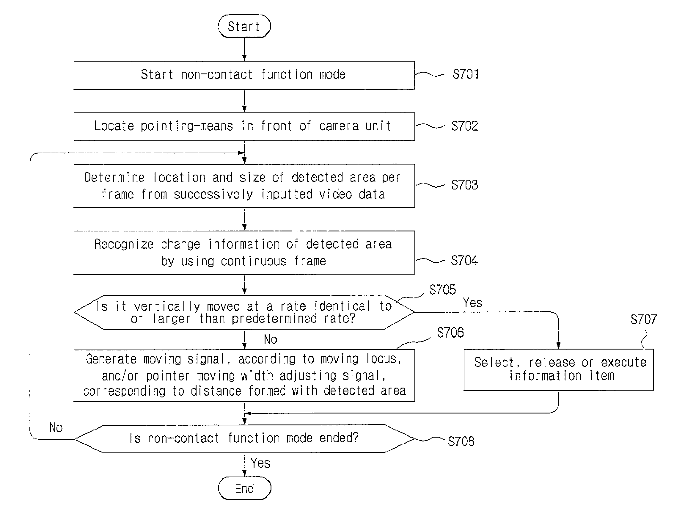
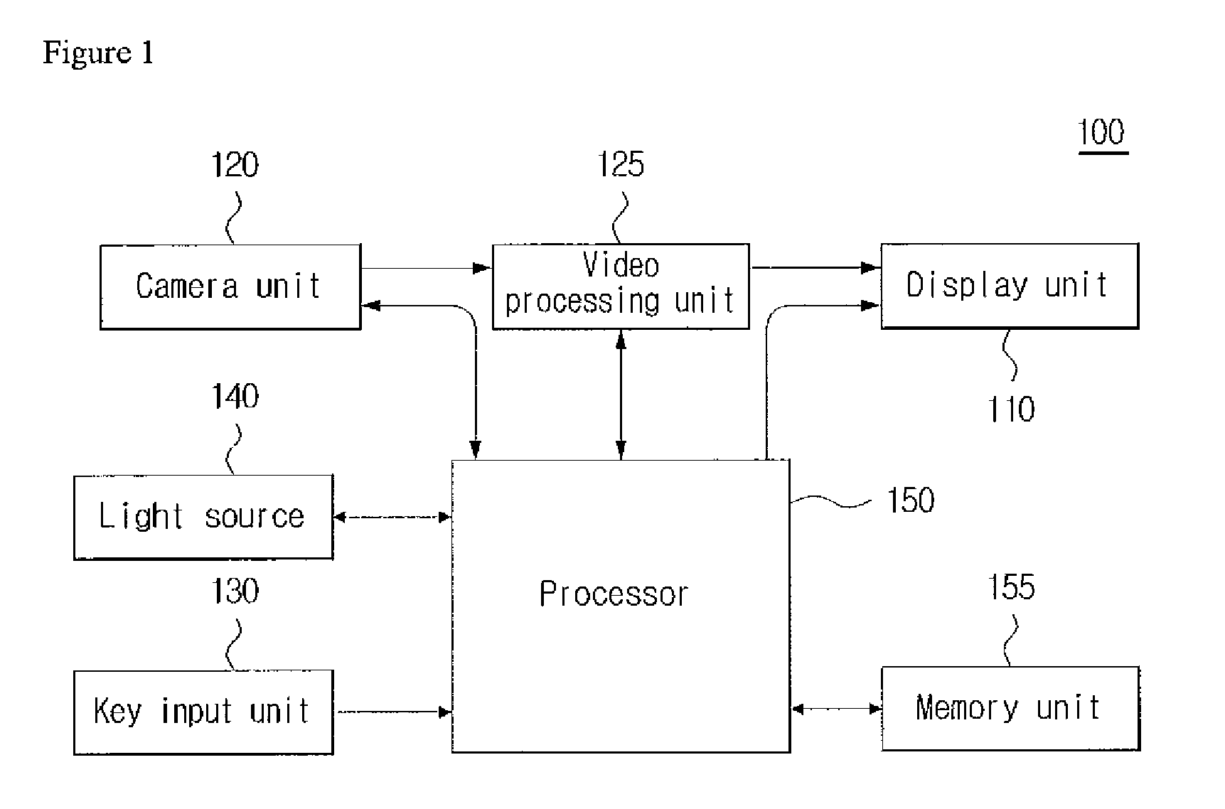
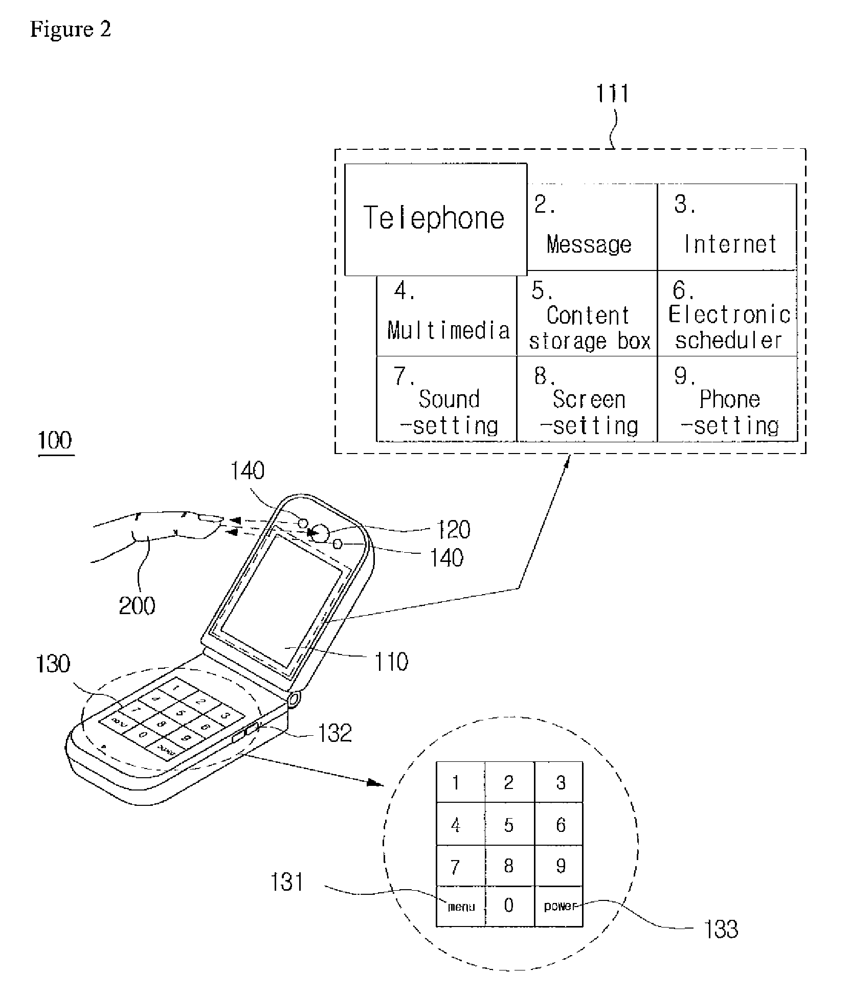
A non-contract selecting device is disclosed. The non-contract selecting device include a light source, emitting light to an outside; a camera unit, generating and outputting a video signal corresponding to an external video; a video data generating unit, generating video data corresponding to the video signal; and an identity unit, detecting a location of a detected area formed by light, reflected by pointing-means and inputted, of the light emitted from the video data in units of each frame, recognizing a moving locus of the detected area by comparing at least two continuous frames and generating and outputting corresponding change information. With the present invention, the function-selecting can be more quickly and easily and increase making the most use of elements.

Description

CROSS-REFERENCE TO RELATED APPLICATIONS[0001]This application claims foreign priority benefits under 35 U.S.C. .sctn. 119(a)-(d) to PCT / KR2007 / 002126, filed Apr. 30, 2007, which is hereby incorporated by reference in its entirety.BACKGROUND[0002]1. Technical Field[0003]The present invention relates to a function selecting method by using a camera, more specifically to a device and method capable of non-contactly selecting a function by using a camera.[0004]2. Description of the Related Art[0005]Today's remarkable development of electronic and communication technologies allows a user to use various functions such as Internet surfing, video communication, moving picture or music playback, and satellite broadcast watching by using a digital home appliance (e.g. a computer and a digital camera) or a portable communication terminal. Accordingly, a key inputting method for efficiently selecting desired functions is requested for a user to enjoy more various functions.[0006]The most favori...

Claims


Application Information

Patent Timeline
IPC IPC(8): G06F3/033H04N5/225
CPCH04N5/23203G06F3/0304H04N23/66
Inventor KIM, DONG-JINJOE, ZEENO
Owner MILA CO LTD
Learn More