Solid electrolytic capacitor

a solid electrolytic capacitor and capacitor technology, applied in the direction of capacitors, basic electric elements, electrical equipment, etc., can solve the problems of difficult to achieve self-alignment properties in solder reflow mounting, degraded leakage current characteristics of products, and difficult to change the electrical connection area of upper/lower surface of terminal portions, etc., to facilitate an increase in capacitance, excellent mountability and mass productivity, and small size

Inactive Publication Date: 2009-05-07
TOKIN CORP
View PDF7 Cites 20 Cited by
  • Summary
  • Abstract
  • Description
  • Claims
  • Application Information

AI Technical Summary

Benefits of technology

[0024]In this invention, a connection pattern comprising an anode portion and a cathode portion is formed on one surface of a substrate, i.e. on a capacitor element connecting surface, and then a capacitor element is mounted. Thus, the area of the cathode portion on the capacitor element connecting surface can be increased to thereby facilitate an increase in capacitance, so that it is possible to obtain a solid electrolytic capacitor excellent in mountability and mass productivity while being small in size and large in capacitance. Further, by providing three or more anode and cathode terminals on the other surface of the substrate, i.e. on a capacitor mounting electrode surface, it is possible to achieve a reduction in ESL as compared with the conventional two-termina...

Problems solved by technology

Therefore, there has been a problem that it is difficult to change the electrical connection area of an upper surface/lower surface of the terminal portion and, thus, when the capacitance element body serving as a cathode portion is made large, a structural or chemical insulating treatment is required for preventing contact with the anode terminal portion.
Although there is no detailed description about the capacitor mounting electrode surface in Patent Document 1 disclosing the solid electrolytic capacitor improved in volume efficiency, when surface-mounting such an electronic component having the mounting electrodes of one cathode and one anode, there arises a problem such that there is no symmetric property and, when the electrode surface is narrow, there tends to occur the Manhattan phenomenon (component rise) or the like in which the self-alignment property is difficult to achieve in solder reflow mounting.
However, the leakage current characteristics of the product are often degraded due to occurrence of cracks at the insulating resin portions or damage to the capacitor element including the porous portion around the opening holes, caused by mechanical/thermal stresses in the formation of the second opening holes.
Further, there is a problem that if the number of the through holes 22 is increased, the ESL decreases, but the area of the portion contributing to the capacitance of the capacitor also decreases sim...

Method used


Image

  • Solid electrolytic capacitor
  • Solid electrolytic capacitor
  • Solid electrolytic capacitor

Examples


Embodiment Construction

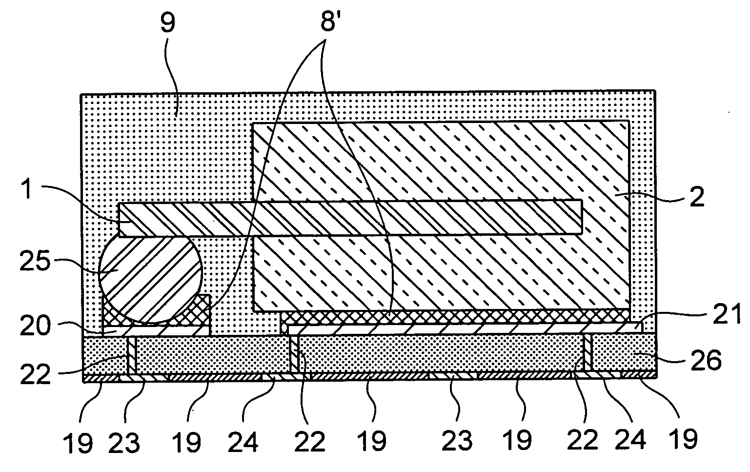
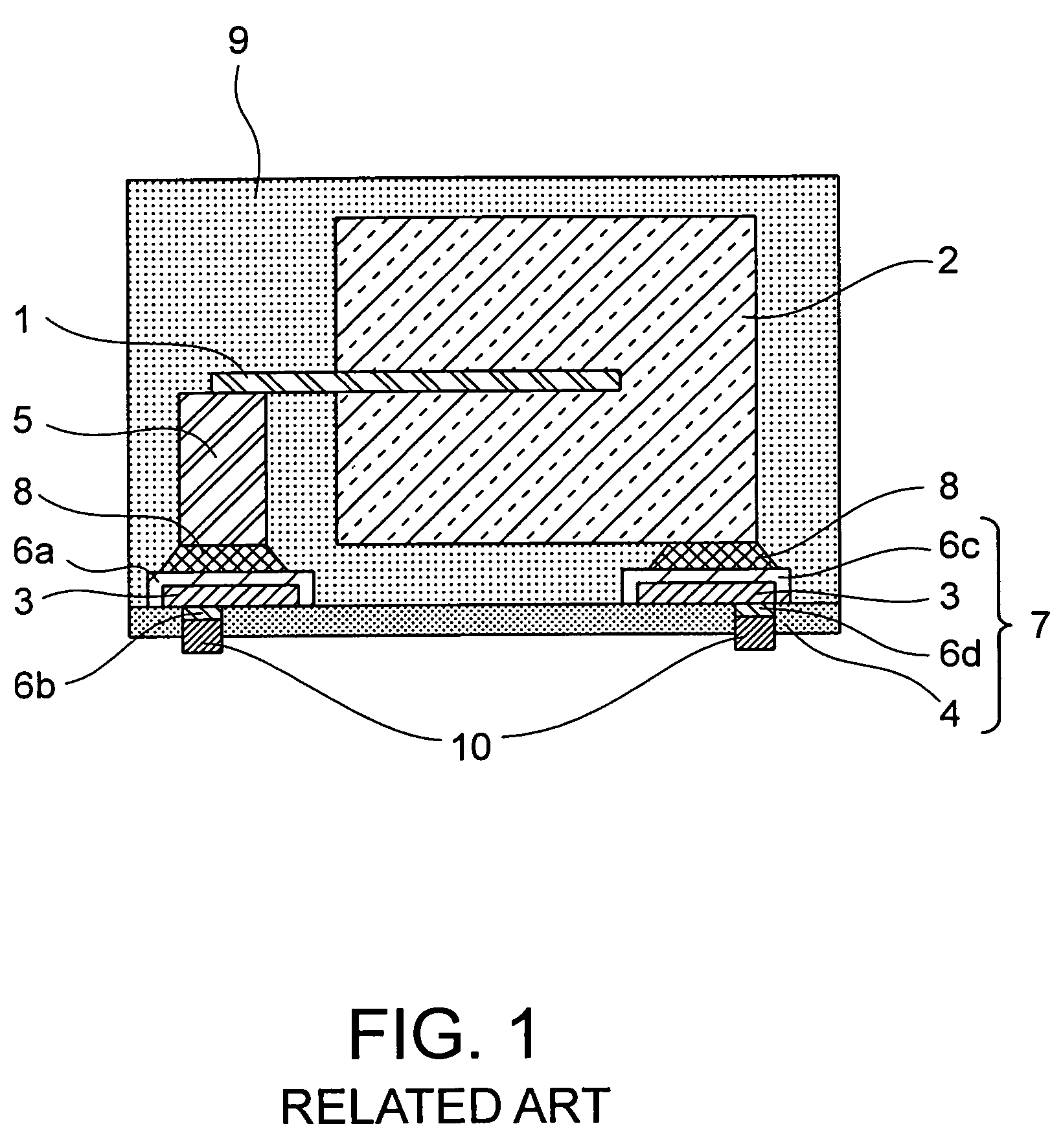
[0037]FIG. 3 is a sectional view for explaining a solid electrolytic capacitor according to an embodiment of this invention. For convenience' sake, the same numerals are assigned to the same portions as those of the solid electrolytic capacitor shown in FIG. 1. An anode material of the solid electrolytic capacitor according to this invention may be any material as long as it is a valve metal that forms an anodized coating serving as a dielectric layer by anodic oxidation, while, a description will be given of, as an example, a tantalum solid electrolytic capacitor using a tantalum metal, which can be easily increased in capacitance by enlarging the surface area with porous powder. A manufacturing method of a capacitor element will be briefly described because of it being a known technique. The shape of the capacitor element, the shape of an anode lead and its drawn-out position, and so on are not particularly limited.

[0038]A capacitor element 2 is formed in the following manner. Ref...


PUM


Abstract

A solid electrolytic capacitor according to this invention includes a capacitor element with a drawn-out anode lead, a conversion substrate mounted with the capacitor element, and a casing resin covering the capacitor element mounted on the conversion substrate. The conversion substrate has, on one surface thereof, a connection pattern composed of an anode portion connected to the anode lead and a cathode portion connected to the body of the capacitor element. The conversion substrate further has, on another surface thereof on the side opposite to the foregoing one surface, a terminal pattern composed of an anode terminal and a cathode terminal connected to the anode portion and the cathode portion through the conversion substrate, respectively. The terminal pattern differs from the connection pattern.

Description

[0001]This application is based upon and claims the benefit of priority from Japanese Patent Application No. 2006-278420, filed on Oct. 12, 2006, the disclosure of which is incorporated herein in its entirety by reference.BACKGROUND OF THE INVENTION[0002]This invention relates to a solid electrolytic capacitor having a plurality of mounting electrodes, for use mainly in power supply circuits of various devices in the electric / electronic / communication fields.BACKGROUND ART[0003]In recent years, a reduction in size and thickness and an increase in functionality of electronic devices have been advanced. As one of effective techniques for realizing it, an increase in circuit driving frequency is cited. To cope with this, a reduction in equivalent series inductance (hereinafter referred to as ESL) and an increase in capacitance are becoming a major subject in solid electrolytic capacitors.[0004]As regards the increase in capacitance, it becomes important how to reduce the volume occupied...

Claims


Application Information

Patent Timeline
IPC IPC(8): H01G9/15H01G9/042
CPCH01G9/15H01G9/012
Inventor SHIMIZU, KUNIHIKOKATOH, KAZUYUKIYOSHIDA, KATSUHIRO
Owner TOKIN CORP
Why Eureka
Try Eureka