
Cartridge for an ejectable compound

a cartridge and compound technology, applied in the field of cartridges, can solve the problems of large total length of incorrectly assembled cartridges and user inability to correctly insert, and achieve the effect of high reliability of applications

Active Publication Date: 2009-05-14
HILTI AG
View PDF2 Cites 5 Cited by
  • Summary
  • Abstract
  • Description
  • Claims
  • Application Information

AI Technical Summary

Benefits of technology

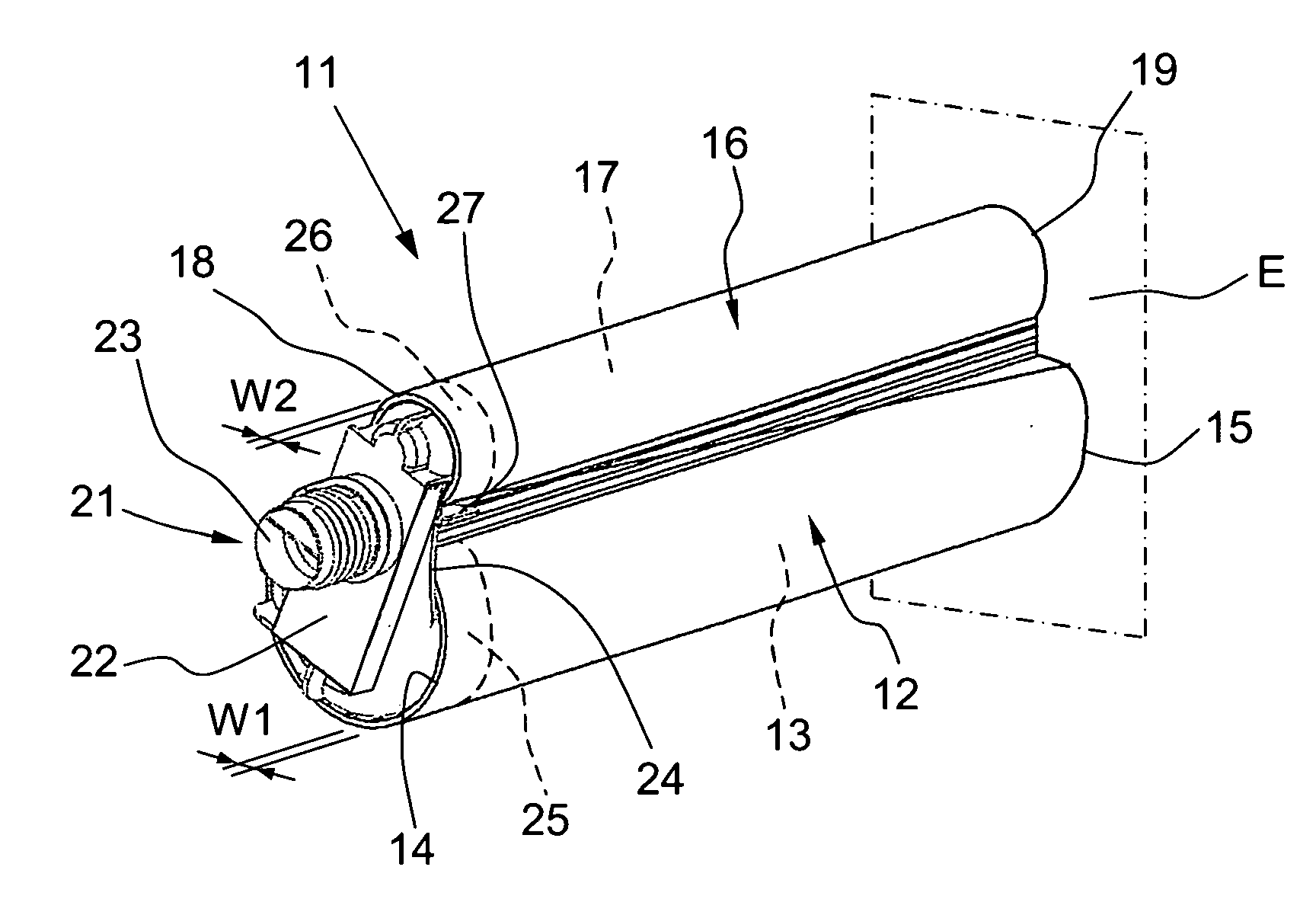
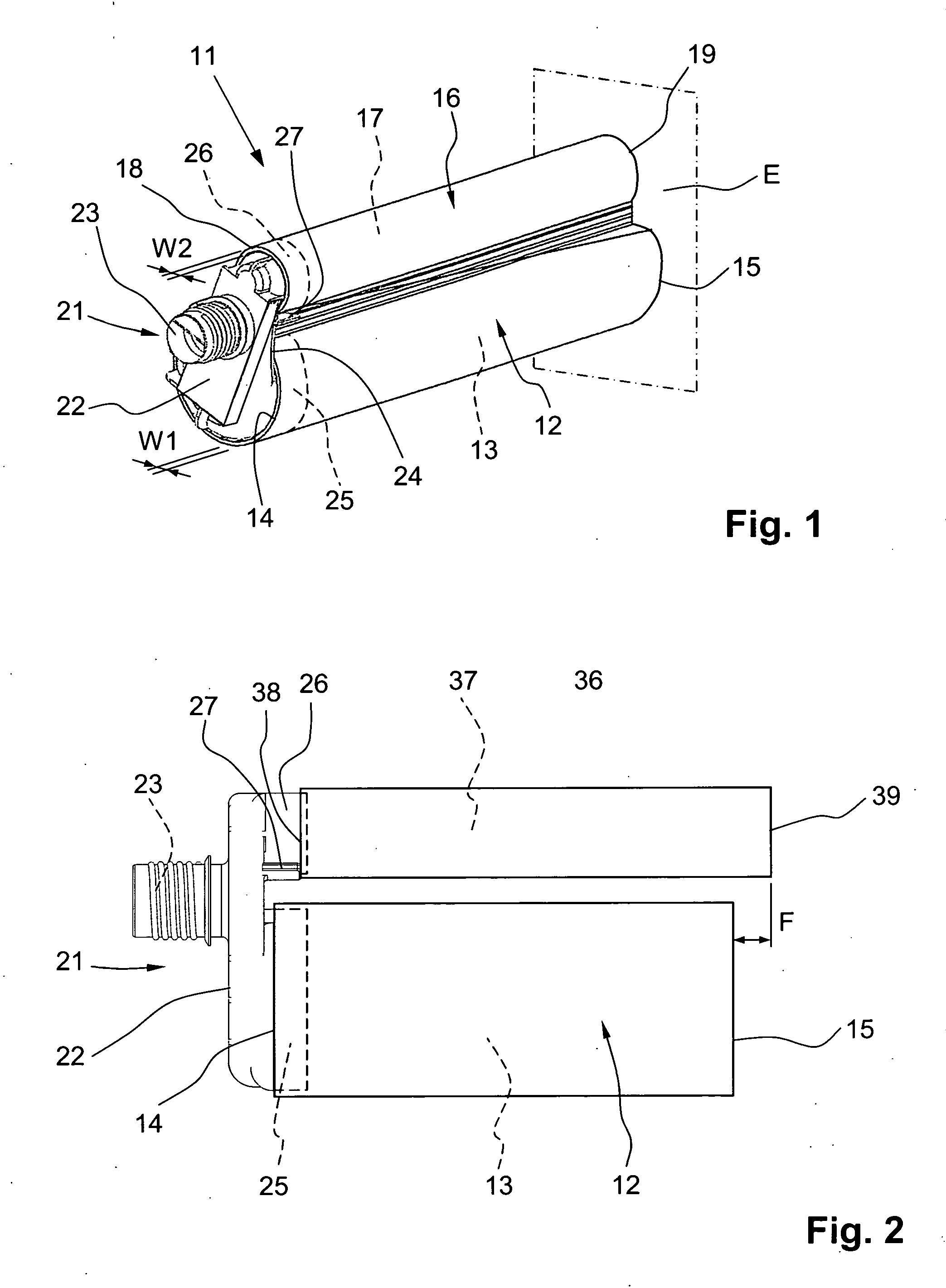
[0011]The at least one guide element prevents the joining of a receptacle with the one guide portion at the head part when the receptacle does not match the guide portion in question. When a head part which is not suitable for the receptacle is arranged at this receptacle, the total length of the incorrectly assembled cartridge is so large that the user cannot correctly insert it into the receptacle of an ejection device. Accordingly, the user immediately notices that there is something wrong with this cartridge and can react accordingly before the start of the ejection process. This prevents the compound to be ejected from being ejected of an incorrectly assembled cartridge and the consequent disadvantages. The at least one guide element substantially forms a coding at the head part.
[0015]In another embodiment according to the invention, the at least one guide element is a recess which is arranged in the contact surface and into which an insertion projection protruding from the corresponding end of the respective receptacle can be inserted. When a receptacle which does not match the corresponding guide portion is joined with the latter, the insertion projection at the corresponding end of the receptacle abuts at the contact surface of the head part so that the incorrectly joined cartridge likewise has an excess length with the above-mentioned advantages for visual and tactile perception. A correct joining of an incorrectly oriented receptacle is likewise prevented because the insertion projection at the receptacle cannot penetrate into the recess in the contact surface of the head part. When the receptacle is joined with the respective guide portion in the reverse manner so that the insertion projection comes to rest remote of the head part, this insertion projection which protrudes beyond the end remote of the head part prevents the complete cartridge comprising a head part and at least one receptacle from being correctly introduced or inserted into the receptacle of an ejection device.
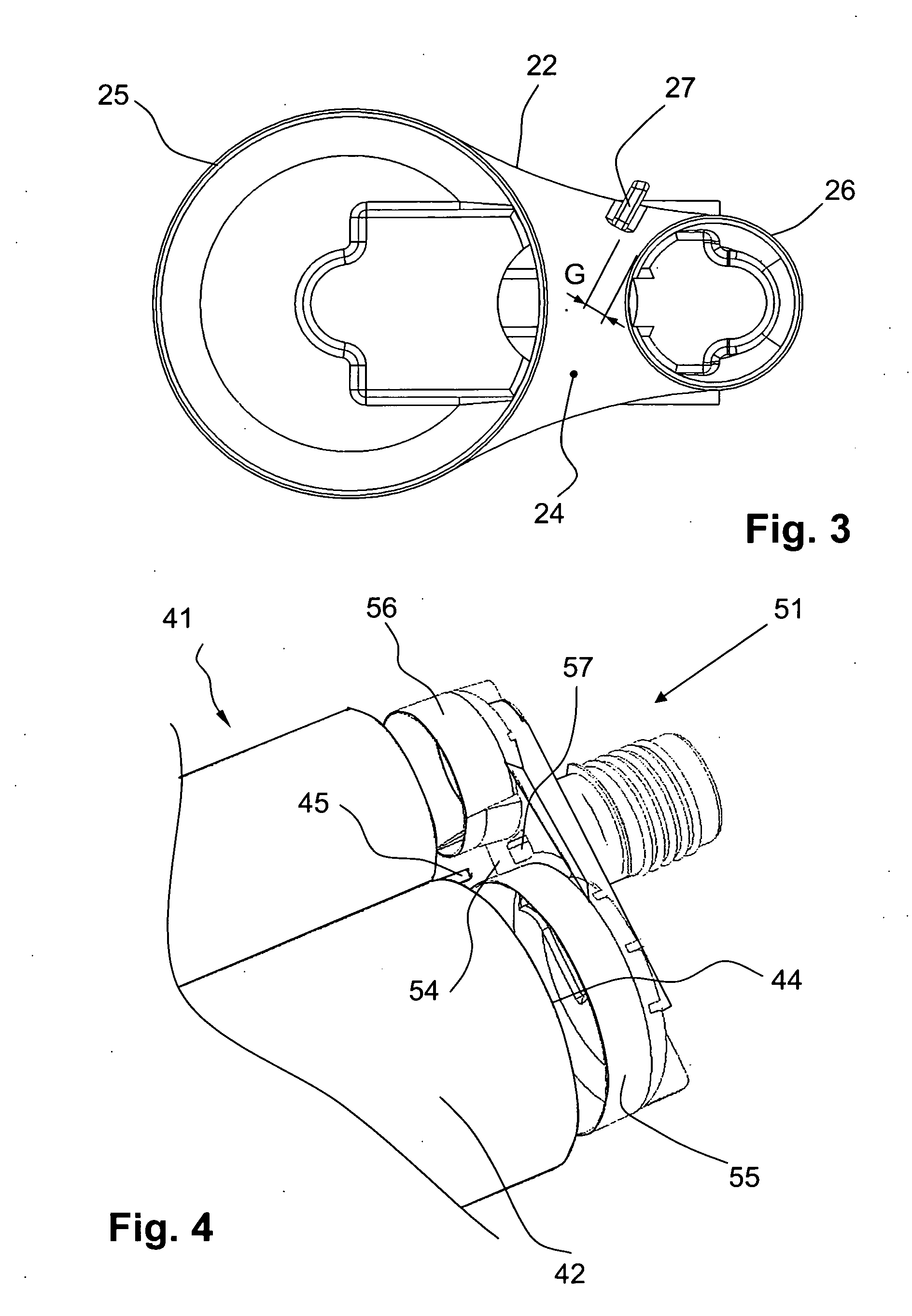
[0016]The at least one guide portion is preferably a circumferential wall portion projecting from the contact surface of the head part, and the at least one guide element is arranged on the inner side of this wall portion. This arrangement also prevents the unintentional use of an incorrectly assembled cartridge in an ejection device in case of head parts in which the receptacle is received by the corresponding guide portion when they are joined.

Problems solved by technology

When a head part which is not suitable for the receptacle is arranged at this receptacle, the total length of the incorrectly assembled cartridge is so large that the user cannot correctly insert it into the receptacle of an ejection device.

Method used


Image

  • Cartridge for an ejectable compound
  • Cartridge for an ejectable compound
  • Cartridge for an ejectable compound

Examples


Embodiment Construction

[0024]The cartridge 11 shown in FIGS. 1 and 3 serves as container for a compound which can be ejected by an ejection device, not shown, and includes two receptacles 12 and 16 and a head part 21. The hollow-cylindrical receptacle 12 has a receptacle chamber 13 for an A component of the compound and a thickness W1 which extends between the side of the receptacle 12 facing the receptacle chamber 13 and the side of the receptacle 12 that is directed radially outwardly. The hollow-cylindrical receptacle 16 has a receptacle chamber 17 for a B component of the compound to be ejected and a wall thickness W2 which extends between the side of the receptacle 16 facing the receptacle chamber 17 and the side of the receptacle 16 which is directed radially outwardly. The receptacle 16 has a receptacle chamber 17 with a smaller cross-section than the receptacle 12.

[0025]The head part 21 has a base plate 22 with an outlet opening 23 for the compound and, at a contact surface 24 of the base plate 22...


PUM


Abstract

A cartridge (11) used as a container for a compound that can be ejected by an ejection device, has two receptacles (12, 16) and a head part (21), each receptacle (12, 16) having a receptacle chamber (13, 17) for components of the compound with the head part (21) having a base plate (22) with an outlet opening (23) for the compound and, at a contact surface (24) of the base plate (22), two guide portions (25, 26) for joining to an end (14, 18) of the corresponding receptacle (12, 16), a guide element for the receptacle (16) arranged adjacent to the guide portion (26) at the contact surface (24) of the head part (21).

Description

BACKGROUND OF THE INVENTION[0001]1. Field of the Invention[0002]The invention relates to a cartridge as a container for a compound that can be ejected by an ejection device and having at least one receptacle with a receiving chamber for the compound, and a head part having a base plate with an outlet opening for the compound and, at a contact surface of the base plate, at least one guide portion for coupling with an end of the receptacle.[0003]2. Description of the Prior Art[0004]A cartridge of this kind serves as a storage package of the compound to be ejected. The cartridge can be placed in an exchangeable manner in a receptacle of an ejection device such as a dispenser. The compound, for example, a mortar compound or sealing compound, is arranged either directly or packaged, e.g., in a foil bag, in the receptacle chamber of the receptacle. The compound located in the cartridge is applied to an application site with the ejection device.[0005]DE 91 00 054 U1 discloses a cartridge o...

Claims


Application Information

Patent Timeline
Patent Type & Authority Applications(United States)
IPC IPC(8): B41J2/175
CPCB65D81/3283B65D81/325Y02W90/10
Inventor OSTERMEIER, PETERHEIBERGER, FRANZLOESCHKY, INGOSTROBEL-SCHMIDT, RAINERHEFELE, CHRISTIAN
Owner HILTI AG
Learn More