
Cutting devices

a cutting device and cutting head technology, applied in the direction of metal sawing devices, wood working safety devices, manufacturing tools, etc., can solve the problems of difficult mounting and removal of guard plates, difficult to smoothly perform cutting operations, and difficult to prevent kickbacks from claws, so as to reduce potential troubles in performing operations

Active Publication Date: 2009-06-25
MAKITA CORP
View PDF19 Cites 16 Cited by
  • Summary
  • Abstract
  • Description
  • Claims
  • Application Information

AI Technical Summary

Benefits of technology

[0011]One embodiment of the present invention is an improved cutting device constructed to reduce potential troubles in performing the operations for removing a guard device and a kickback preventing claw member from a splitter.
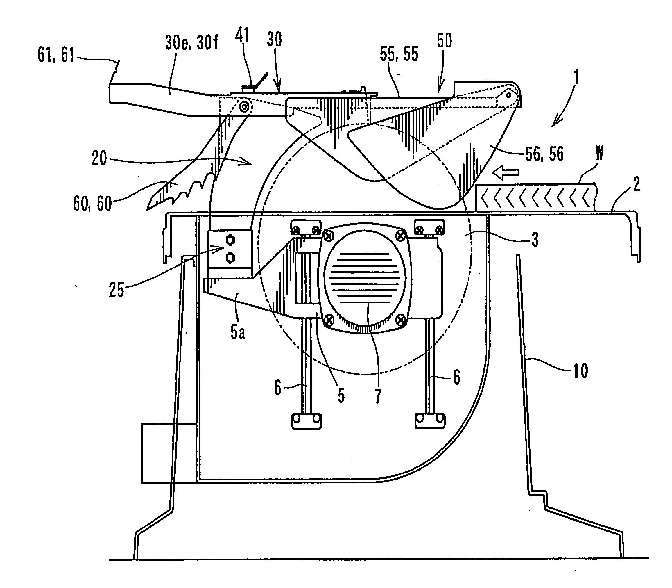
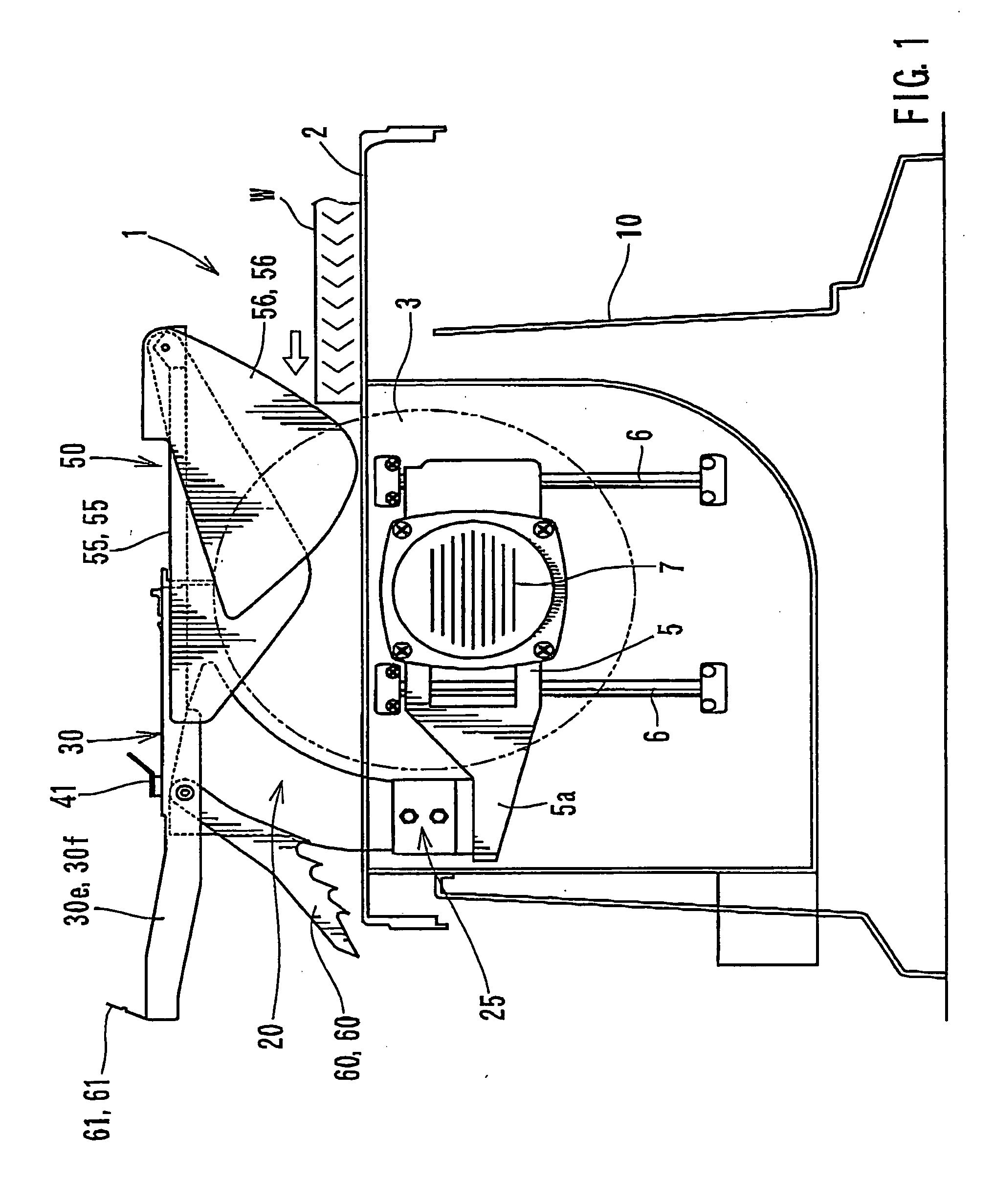
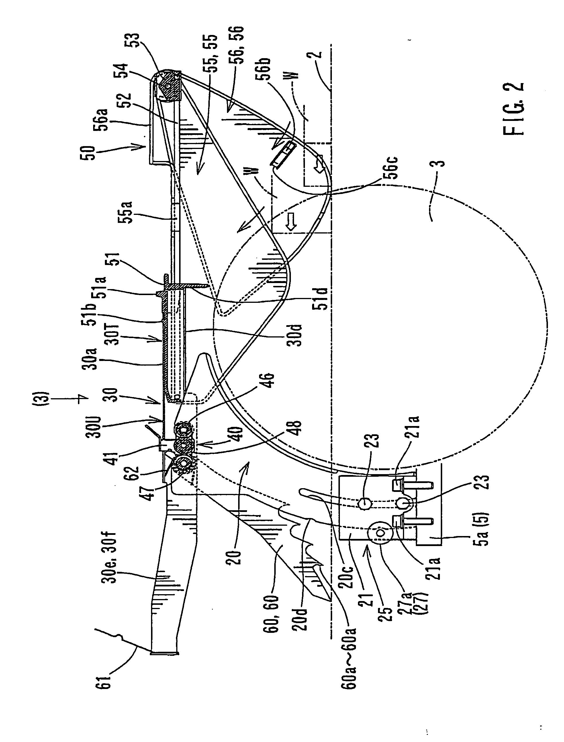
[0012]In another embodiment of the present invention, cutting devices are taught that include a table for placing a workpiece thereon, and a saw blade protruding from an upper surface of the table. A splitter positioned on the front side with respect to a cutting direction of the saw blade and in alignment with the saw blade. A guard device is provided for covering the saw blade. A kickback preventing claw member prevents the workpiece from being forced upward by the saw blade after the workpiece has been cut by the saw blade. A mount frame is detachably mounted to an upper portion of the splitter. The guard device and the kickback preventing claw member are supported on the mount frame, so that the guard device and the kickback preventing claw can be removed together from the splitter.

Problems solved by technology

This phenomenon is called “kickback phenomenon.” When this phenomenon occurs, it is difficult to smoothly perform the cutting operation.
In this configuration, a problem occurs such that the mounting and removing operations of the guard plate and the kickback preventing claw members are very difficult when such operations are necessary for changing the saw blade.

Method used


Image

  • Cutting devices
  • Cutting devices
  • Cutting devices

Examples


Embodiment Construction

[0028]Each of the additional features and teachings disclosed above and below may be utilized separately or in conjunction with other features and teachings to provide improved cutting devices. Representative examples of the present invention, which examples utilize many of these additional features and teachings both separately and in conjunction with one another, will now be described in detail with reference to the attached drawings. This detailed description is merely intended to teach a person of skill in the art further details for practicing preferred aspects of the present teachings and is not intended to limit the scope of the invention. Only the claims define the scope of the claimed invention. Therefore, combinations of features and steps disclosed in the following detailed description may not be necessary to practice the invention in the broadest sense, and are instead taught merely to particularly describe representative examples of the invention. Moreover, various feat...


PUM

PropertyMeasurementUnit
widthaaaaaaaaaa
distanceaaaaaaaaaa
thicknessaaaaaaaaaa

Abstract

A cutting including a saw blade protruding from an upper surface of the table can include a splitter positioned on the front side with respect to a cutting direction of the saw blade and in alignment with the saw blade. A guard device is provided for covering the saw blade. A kickback preventing claw member prevents the workpiece from being forced upward by the saw blade after the workpiece has been cut by the saw blade. A mount frame is detachably mounted to an upper portion of the splitter. The guard device and the kickback preventing claw member are supported on the mount frame, so that the guard device and the kickback preventing claw can be removed separately or together from the splitter.

Description

BACKGROUND OF THE INVENTION[0001]1. Field of the Invention[0002]This is a Divisional of application Ser. No. 11 / 519,942, filed Sep. 13, 2006. This application claims priority to Japanese patent application serial number 2005-268614, the contents of which are incorporated herein by reference.[0003]The present invention relates to cutting devices, and in particular to table saws having a table for placing workpieces thereon and a saw blade partially protruding upward from the upper surface of the table.[0004]2. Description of the Related Art[0005]Table saws have a table for placing workpieces thereon and a circular saw blade that partially protrudes upward from the upper surface of the table, so that workpieces may be cut by moving workpieces along the upper surface of the table toward the saw blade in a direction parallel to the surface of the saw blade. It has been known to provide a guard device in order to prevent potential interference of the other articles with the upper portion...

Claims


Application Information

Patent Timeline
Patent Type & Authority Applications(United States)
IPC IPC(8): B26D1/18B26D7/22
CPCB23D47/04B27G19/08B27G19/02Y10S83/01Y10T83/2077Y10T83/732Y10T83/773Y10T83/7734Y10T83/872
Inventor SHIBATA, YOSHINORI
Owner MAKITA CORP
Learn More