Image forming apparatus monitoring system and method therefor

a technology for image forming apparatus and monitoring system, which is applied in the direction of fault response, digital output to print units, instruments, etc., and can solve the problem of high cost of upgrading the firmwar

Active Publication Date: 2009-06-25
CANON KK
View PDF8 Cites 34 Cited by
  • Summary
  • Abstract
  • Description
  • Claims
  • Application Information

AI Technical Summary

Problems solved by technology

Accordingly, in the conventional method, high costs for upgrading the firmware may arise.

Method used


Image

  • Image forming apparatus monitoring system and method therefor
  • Image forming apparatus monitoring system and method therefor
  • Image forming apparatus monitoring system and method therefor

Examples


Embodiment Construction

[0035]Various exemplary embodiments, features, and aspects of the present invention will now be herein described in detail below with reference to the drawings. It is to be noted that the relative arrangement of the components, the numerical expressions, and numerical values set forth in these embodiments are not intended to limit the scope of the present invention.

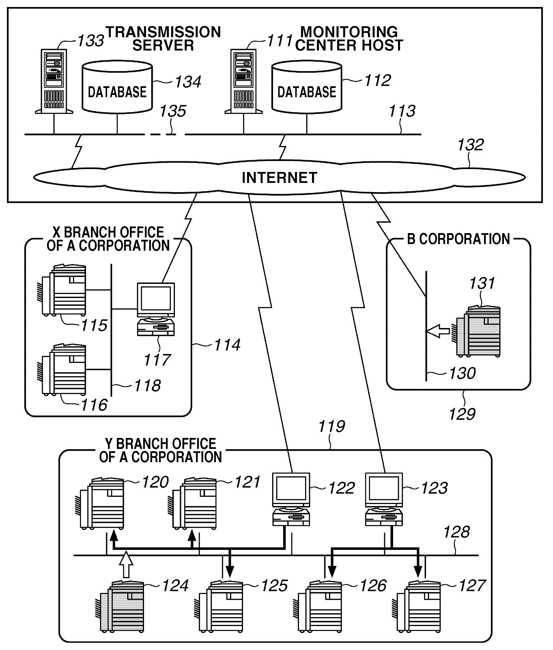
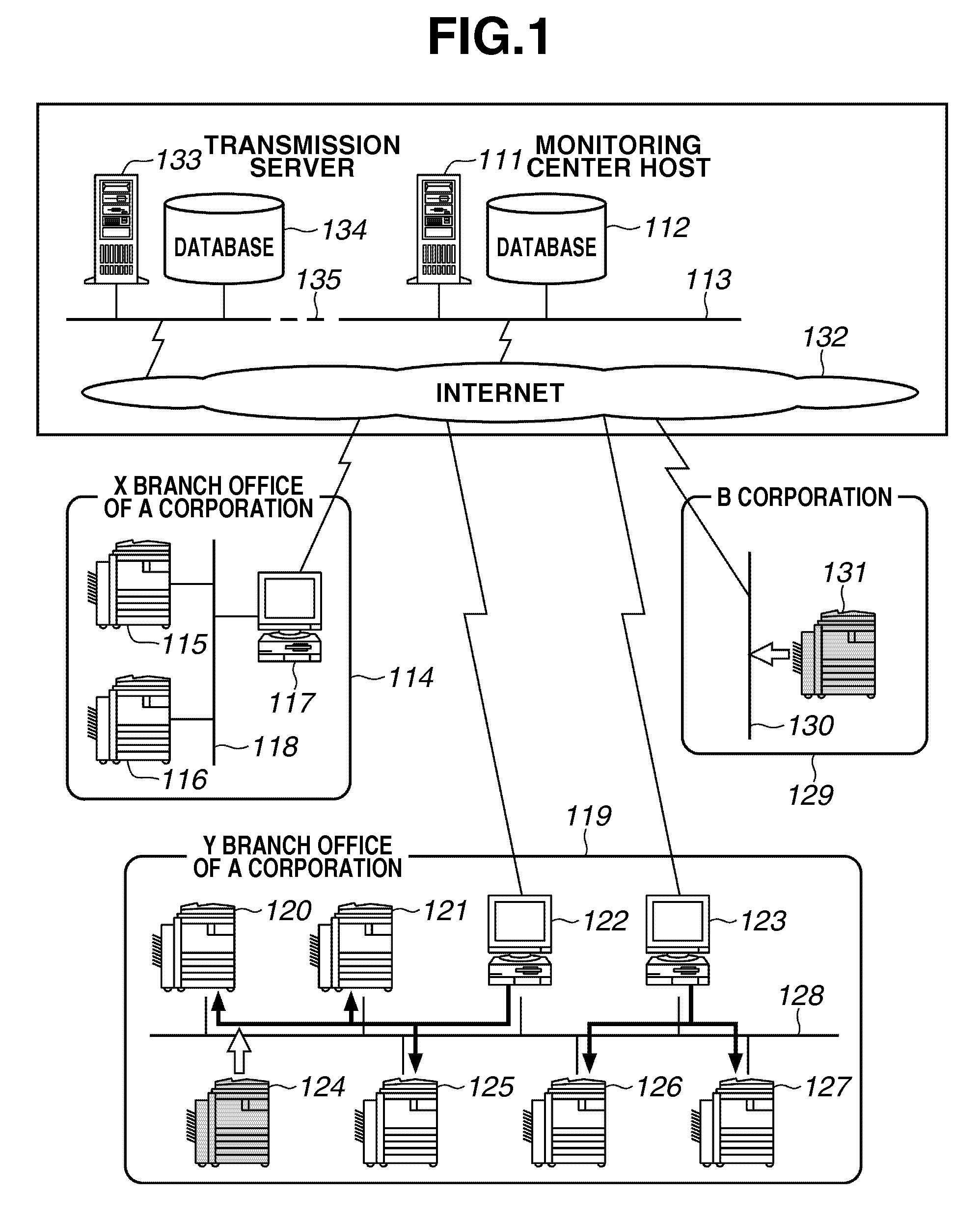
[0036]FIG. 1 illustrates an example of a configuration of an image forming apparatus monitoring system according to an exemplary embodiment of the present invention.

[0037]Referring to FIG. 1, the image forming apparatus monitoring system includes a monitoring center host (monitoring server) 111. Furthermore, the image forming apparatus monitoring system includes a database112. The database 112 is a database that functions as a history storage unit for storing information related to monitoring, a counter for an image forming apparatus collected from the image forming apparatus installed at a customer's location, error hist...


PUM


Abstract

A monitoring server that monitors an image forming apparatus and detects an error if any has occurred thereon, identifies a type of firmware that has caused the error, and issues an instruction for replacing a version of the identified type of firmware. The image forming apparatus issues, to a transmission server, a request for transmitting a replacement version of the identified type of firmware. The transmission server refers to a firmware version list table to determine another type of firmware whose version is to be replaced in association with the replacement version of the identified type of firmware. The transmission server transmits the replacement version of the identified type of firmware and the determined another type of firmware to the image forming apparatus. The image forming apparatus receives each firmware transmitted from the transmission server and applies the received firmware to the image forming apparatus.

Description

BACKGROUND OF THE INVENTION[0001]1. Field of the Invention[0002]The present invention relates to a system for upgrading firmware of an image forming apparatus. More specifically, the present invention relates to a method for replacing firmware of an image forming apparatus controlled by a plurality of types of firmware.[0003]2. Description of the Related Art[0004]A conventional monitoring system remotely monitors an operation state of a peripheral device, such as an image forming apparatus. In an environment in which the monitoring system like this is used, a conventional method upgrades firmware of an image forming apparatus in the following manner.[0005]That is, in the case where it is necessary to upgrade the firmware due to previously performed version upgrading or an error occurring on the image forming apparatus, a service person in charge must personally visit the customer's business location, where the image forming apparatus is installed. In this case, the service person in...

Claims


Application Information

Patent Timeline
Patent Type & Authority Applications(United States)
IPC IPC(8): G06F15/00G06F15/177G06F11/14
CPCG06F11/1433H04N1/00344H04N1/00973H04N2201/0094H04N1/32625H04N1/32646H04N1/32662H04N1/32609
Inventor NAKAMOTO, HISASHI
Owner CANON KK
Why Eureka
Try Eureka