Dishwasher with multiple wash zones

Inactive Publication Date: 2009-07-16
WHIRLPOOL CORP
View PDF7 Cites 47 Cited by
  • Summary
  • Abstract
  • Description
  • Claims
  • Application Information

AI Technical Summary

Problems solved by technology

One problem associated with contemporary dishwashers is that the utensils may not receive uniform wash treatment depending upon their positioning within a rack in

Method used


Image

  • Dishwasher with multiple wash zones
  • Dishwasher with multiple wash zones
  • Dishwasher with multiple wash zones

Examples


second embodiment

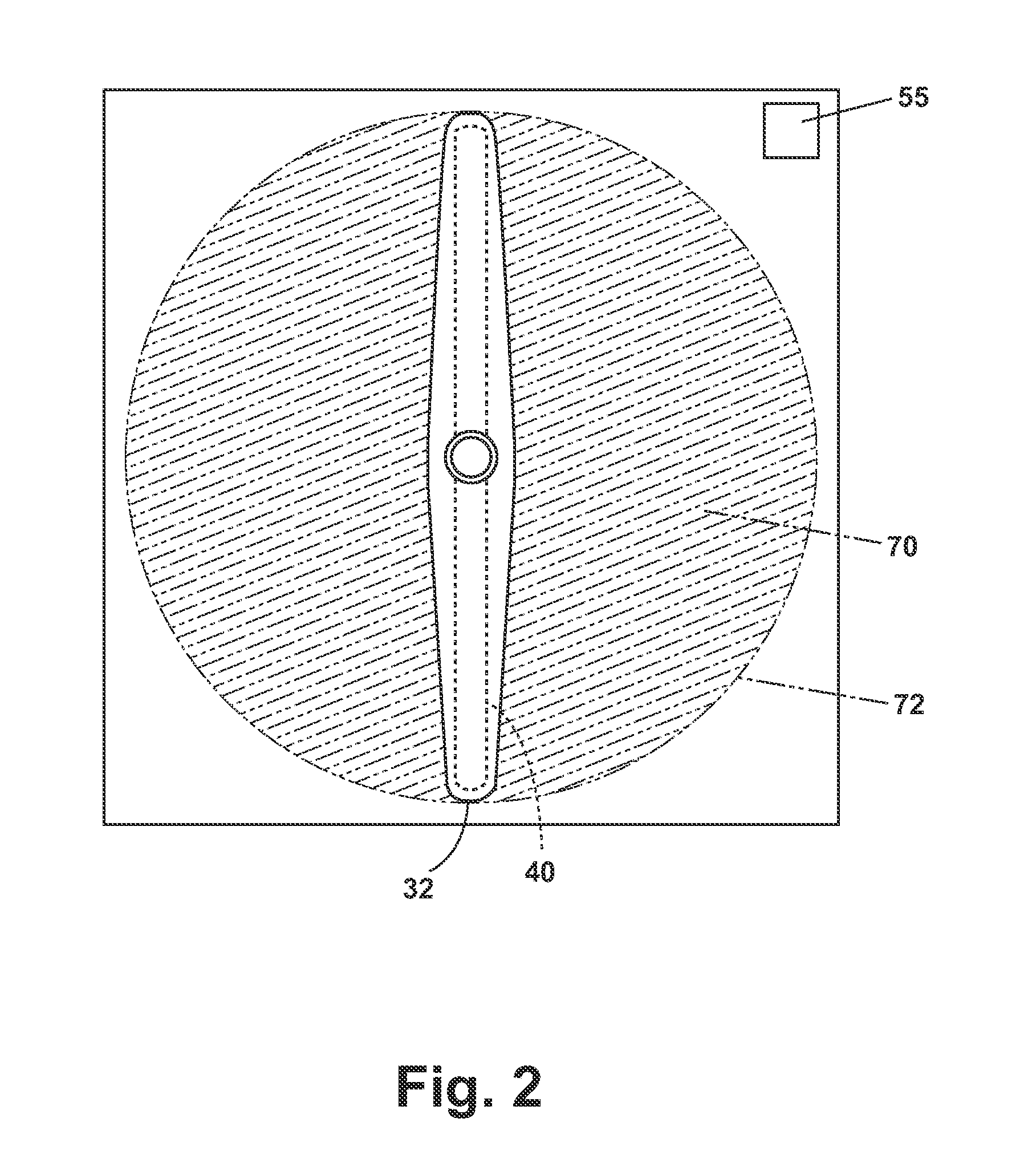
[0023]Other liquid volume controllers according to the invention have been contemplated. the liquid volume controller is depicted in FIGS. 3 and 4, wherein the liquid volume controller is a stop mechanism 164. This stop mechanism 164 may be located beneath a portion of the rotating lower spray arm assembly 32. When the controller 50 signals the stop mechanism 164 the stop mechanism 164 may extend itself such that it is located in the plane of rotation 70 of the rotating lower spray arm assembly 32. The extended stop mechanism 164 obstructs further rotation of the rotating lower spray arm assembly 32 until the stop mechanism 164 is retracted by a signal from the controller 50. FIG. 4 shows that the stop mechanism 164 contacts the rotating lower spray arm assembly 32 when the stream of liquid 166 is fluidly coupled with the disperser 150.

[0024]During operation of the dishwasher 10, the liquid volume controller may be employed to control and increase the volume of the stream of liquid ...

third embodiment

[0025]FIG. 5 is the invention and comprises a liquid volume controller 60 and multiple dispersers in the form of manifolds. The spray manifold 255 is configured to have one spray manifold inlet 260, a spray manifold chamber 262 which may be filled with liquid and at least one spray manifold outlet 264 configured to spray wash liquid into the interior of the wash chamber 24. The stream of liquid from the rotating lower spray arm assembly 32 will be under pressure as it passes through the spray manifold inlet 260, into the spray manifold chamber 262 and out at least one spray manifold outlet 264. As water passes through the spray manifold inlet 260 the spray manifold chamber 262 is filled by the stream of liquid during successive rotations of the rotating lower spray arm assembly 32. Once the spray manifold chamber 262 is filed additional water introduced into the spray manifold inlet 260 will produce a liquid stream out of at least one spray manifold outlet 264. While not shown, a ch...

fourth embodiment

[0027]FIG. 6 is the invention and illustrates a front view of a spray manifold 355. The spray manifold 355 is configured to have one inlet 360, a chamber 362 which may be filled with liquid and at least one outlet 364 configured to spray wash liquid into the interior of the wash chamber 24. The stream of liquid from the rotating lower spray arm assembly 32 will be under pressure as it passes through the inlet 360 into the chamber 362 and out at least one outlet 364. As water passes through the inlet 360, the chamber 362 is filled by the stream of liquid during successive rotations of the rotating lower spray arm assembly 32. While not shown, a check valve can be placed at the spray manifold inlet 360 to stop the back flow of water from the spray manifold 355. Once the chamber 362 is filed additional water introduced into the inlet 360 will produce liquid streams out of at least one outlet 364.


PUM


Abstract

An automatic dishwasher, comprises a wash chamber, a rotating spray arm having an outer periphery or rotation and having at least one outlet for introducing a stream of liquid into the wash chamber, a disperser located within the wash chamber and exteriorly of the outer periphery of the rotating spray arm where during at least a portion of one revolution of the rotating spray arm the disperser is fluidly connected such that the stream of liquid is transferred to the disperser, and a liquid volume controller to control the volume of liquid transferred from the rotating spray arm to the disperser. Wherein the disperser provides an additional source of water spray to utensils in the wash chamber and the liquid volume controller controls the amount of such additional spray.

Description

BACKGROUND OF THE INVENTION[0001]Contemporary dishwashers include a tub defining a wash chamber within which is provided a rack for holding dishes. Typically, there is an upper and lower rack or basket for supporting soiled utensils within the tub. A pump is provided for re-circulating wash liquid throughout the tub to remove soils from the utensils. Rotating spray arms are typically positioned beneath each rack and are supplied liquid from the pump, which effects the rotation of the arm as it is sprayed onto the rack.[0002]One problem associated with contemporary dishwashers is that the utensils may not receive uniform wash treatment depending upon their positioning within a rack in the dishwasher. The rotating arms rotate in a plane about a vertical axis and define a circular outer periphery of the wash arms wherein the majority of the wash liquid is sprayed. The racks tend to be rectangular, which results in the corners of the racks lying beyond the outer periphery where they rec...

Claims


Application Information

Patent Timeline
IPC IPC(8): A47L15/22A47L15/42
CPCA47L15/4246A47L15/22A47L15/4282
Inventor DELGADO, KRISTOPHER LEE
Owner WHIRLPOOL CORP
Why Eureka
Try Eureka