Image forming apparatus

Inactive Publication Date: 2009-07-23
S PRINTING SOLUTION CO LTD
View PDF1 Cites 35 Cited by
  • Summary
  • Abstract
  • Description
  • Claims
  • Application Information

AI Technical Summary

Problems solved by technology

An image forming apparatus with the above described configuration, however, unfortunately, relies on the precisely formed through-holes and / or the rotating shafts to maintain the gaps, and thus often fails to maintain the gaps to the desired preset gaps.

Method used


Image

  • Image forming apparatus
  • Image forming apparatus
  • Image forming apparatus

Examples


Embodiment Construction

[0020]Reference will now be made in detail to exemplary embodiments of the present invention, examples of which are illustrated in the accompanying drawings, wherein like reference numerals refer to like elements throughout. While the embodiments are described with detailed construction and elements to assist in a comprehensive understanding of the various applications and advantages of the embodiments, it should be apparent however that the embodiments can be carried out without those specifically detailed particulars. Also, well-known functions or constructions will not be described in detail so as to avoid obscuring the description with unnecessary detail. It should be also noted that in the drawings, the dimensions of the features are not intended to be to true scale, and may be exaggerated for the sake of allowing greater understanding.

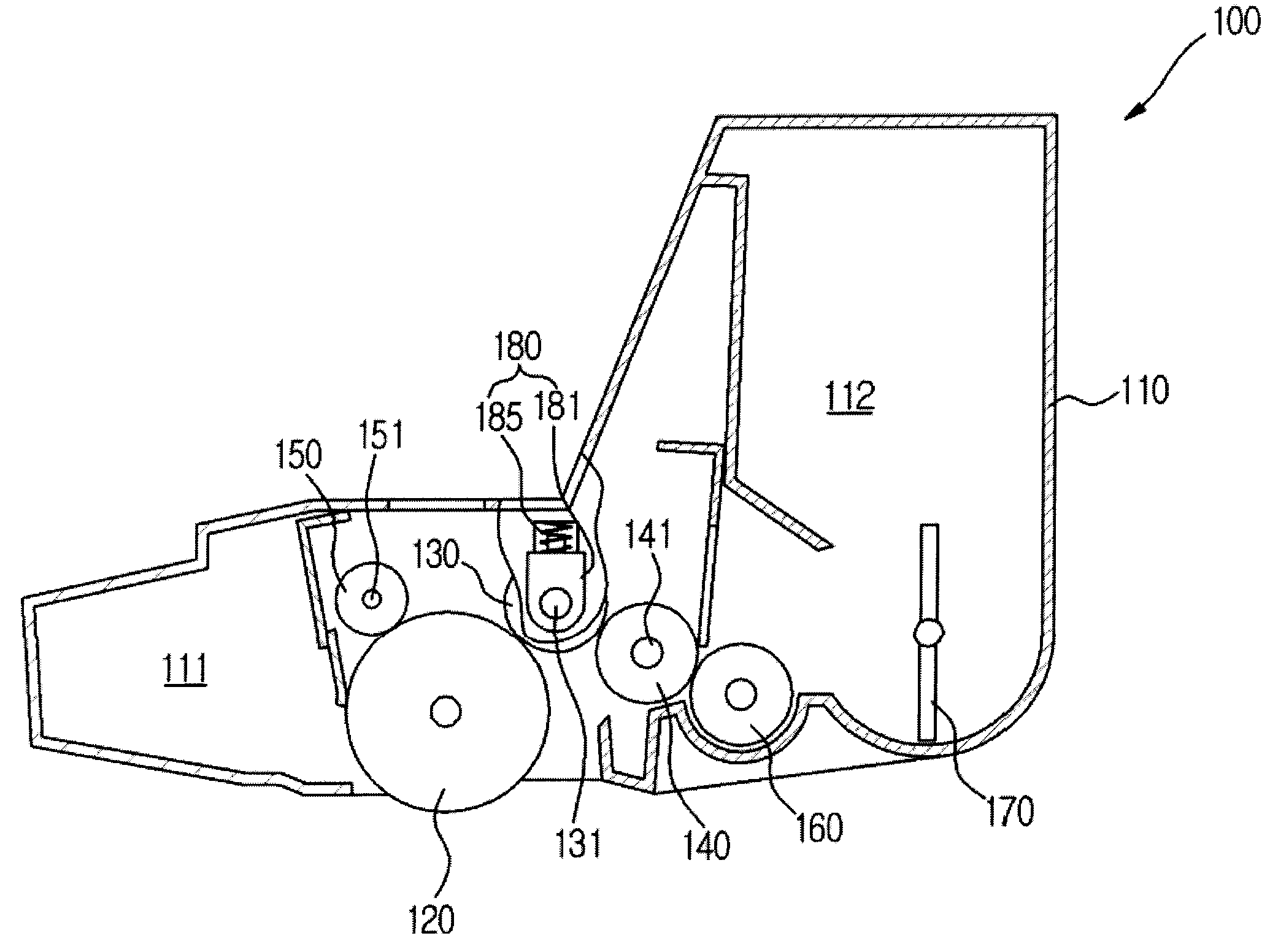
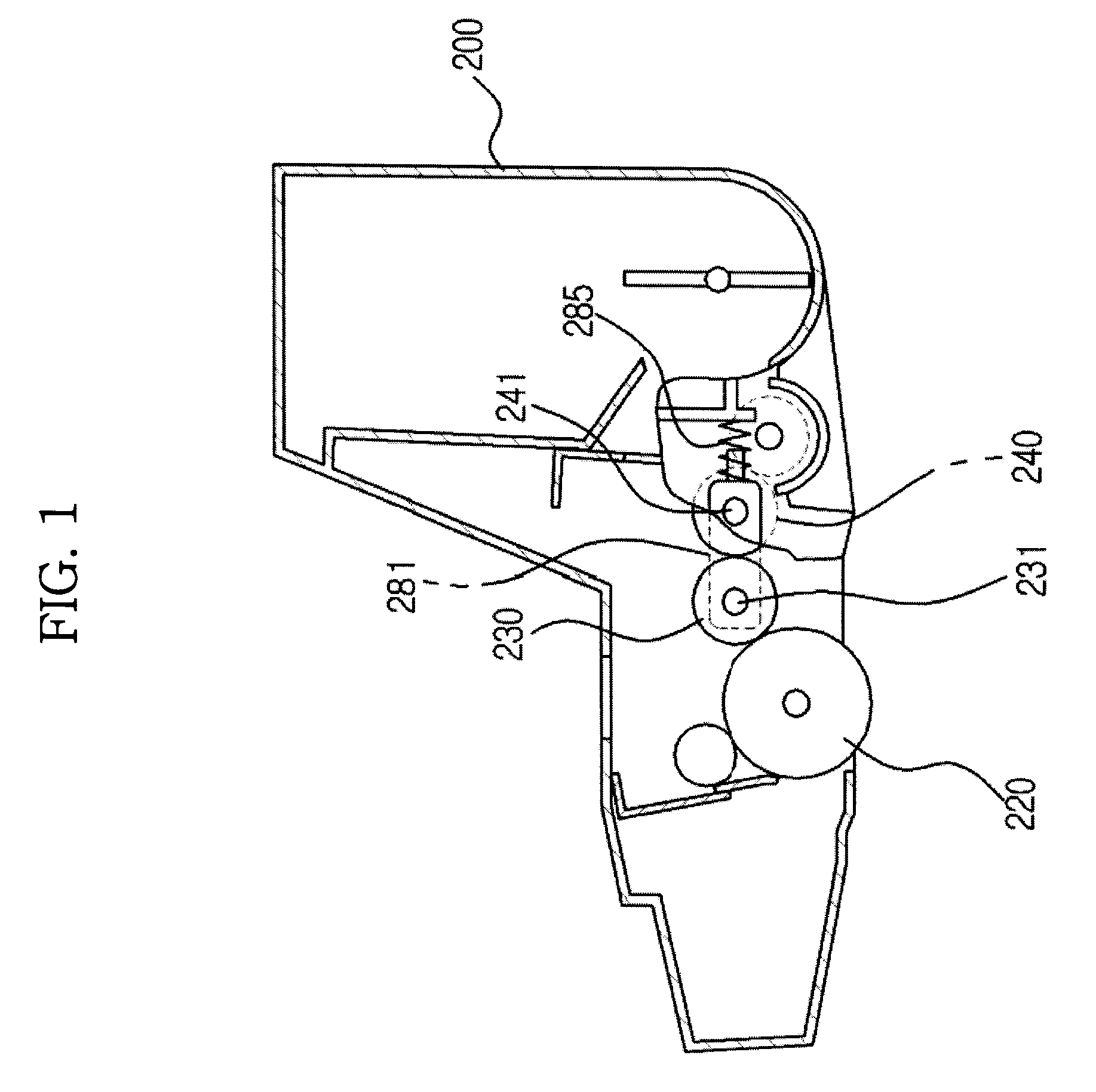
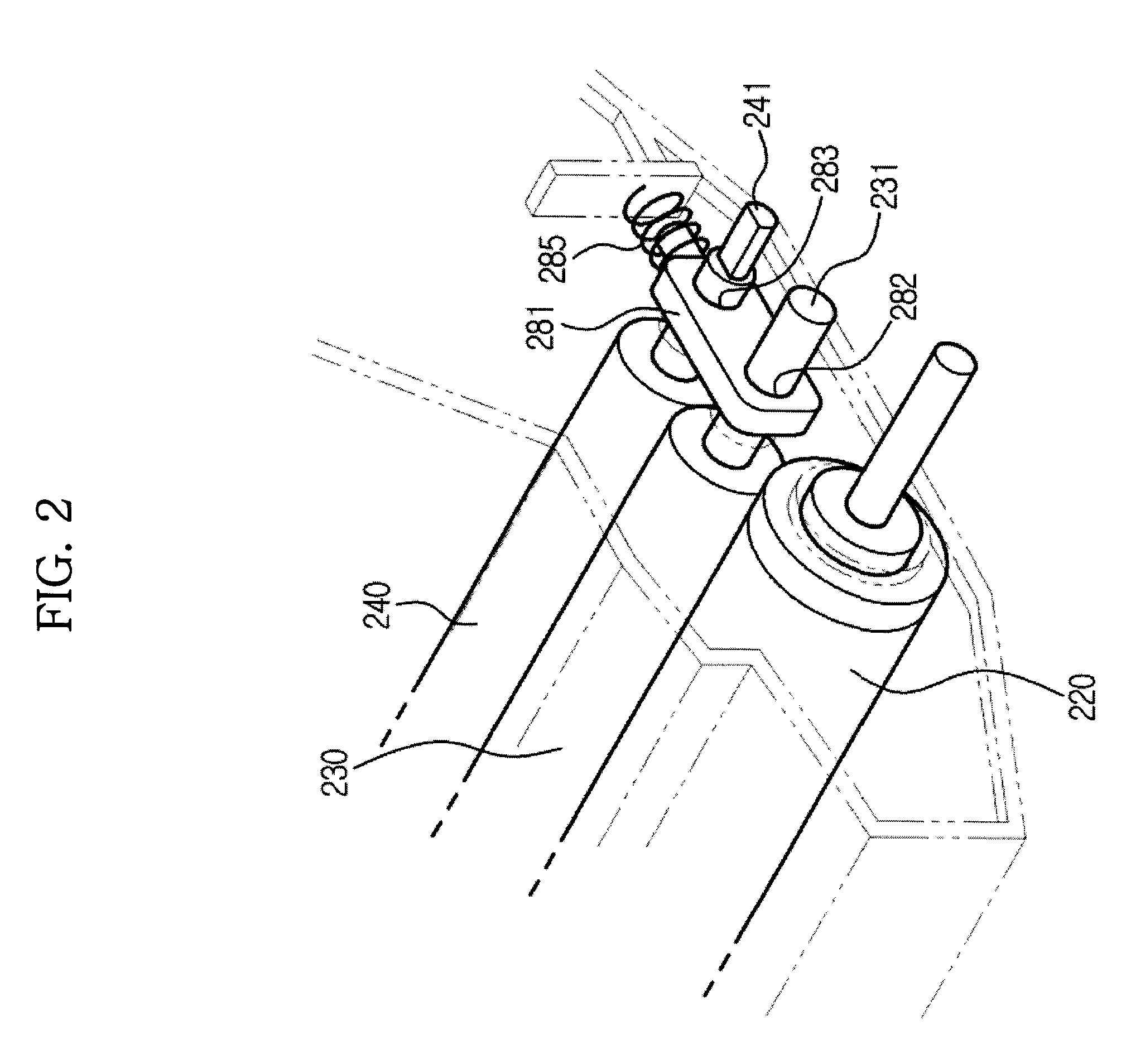
[0021]As shown in FIG. 3, an image forming apparatus according to an embodiment may include a main body 10, which forms an exterior appearance, ...


PUM


Abstract

An image forming apparatus is disclosed. The image forming apparatus includes a photosensitive body, a magnetic roller disposed at a predetermined distance from the photosensitive body, and a donor roller disposed between the photosensitive body and the magnetic roller. The donor roller has a diameter larger than the closest distance between the photosensitive body and the magnetic roller. The image forming apparatus includes gap rings and pressing device to maintain desired gaps between the magnetic roller and the donor roller and between the donor roller and the photosensitive body.

Description

CROSS-REFERENCE TO RELATED APPLICATION[0001]This application claims the benefit of Korean Patent Application No. 2008-0006054, filed on Jan. 21, 2008 in the Korean Intellectual Property Office, the disclosure of which is incorporated herein by reference.BACKGROUND OF THE INVENTION[0002]1. Field of the Invention[0003]The present invention relates to an image forming apparatus, and more particularly, to an image forming apparatus capable of maintaining a gap between a donor roller and a magnetic roller and a gap between a donor roller and a photosensitive body to a predetermined gap.[0004]2. Description of the Related Art[0005]An image forming apparatus refers to an apparatus, in which an electrostatic latent image corresponding to a desired image is formed on a photosensitive body by an exposure unit, such as, e.g., a laser scanning unit. The electrostatic latent image is developed into a visible image by the use of developer, and the visible image is transferred and fused onto a pri...

Claims


Application Information

Patent Timeline
IPC IPC(8): G03G15/09
CPCG03G15/0921G03G15/0813G03G15/0806G03G15/0815G03G2215/0634
Inventor PARK, GYEONG HOCHOE, WON
Owner S PRINTING SOLUTION CO LTD
Why Eureka
Try Eureka