Electronic power supply device for light-emitting diode

a technology of electric power supply device and diode, which is applied in the direction of electric variable regulation, process and machine control, instruments, etc., can solve the problems and achieve the effect of reducing the efficiency conversion of energy conversion system and extending the service life of power supply devi

Inactive Publication Date: 2009-08-06
PAI HAO CHIN +3
View PDF3 Cites 10 Cited by
  • Summary
  • Abstract
  • Description
  • Claims
  • Application Information

AI Technical Summary

Benefits of technology

[0027]In the electronic power supply device of the present invention, to take into consideration thermal issue that causes reduction of power supply efficiency and conversion, the system heat diction circuit is used to carry out detection and protection of which the operation is detection of temperature and uses preset reference basic value for detection. If the detected temperature is too high, then it is provided to the photo-coupling circuit and the feedback circuit to

Problems solved by technology

If the detected temperature is too high, then it is provided to the photo-coupling circuit and th

Method used


Image

  • Electronic power supply device for light-emitting diode
  • Electronic power supply device for light-emitting diode
  • Electronic power supply device for light-emitting diode

Examples


second embodiment

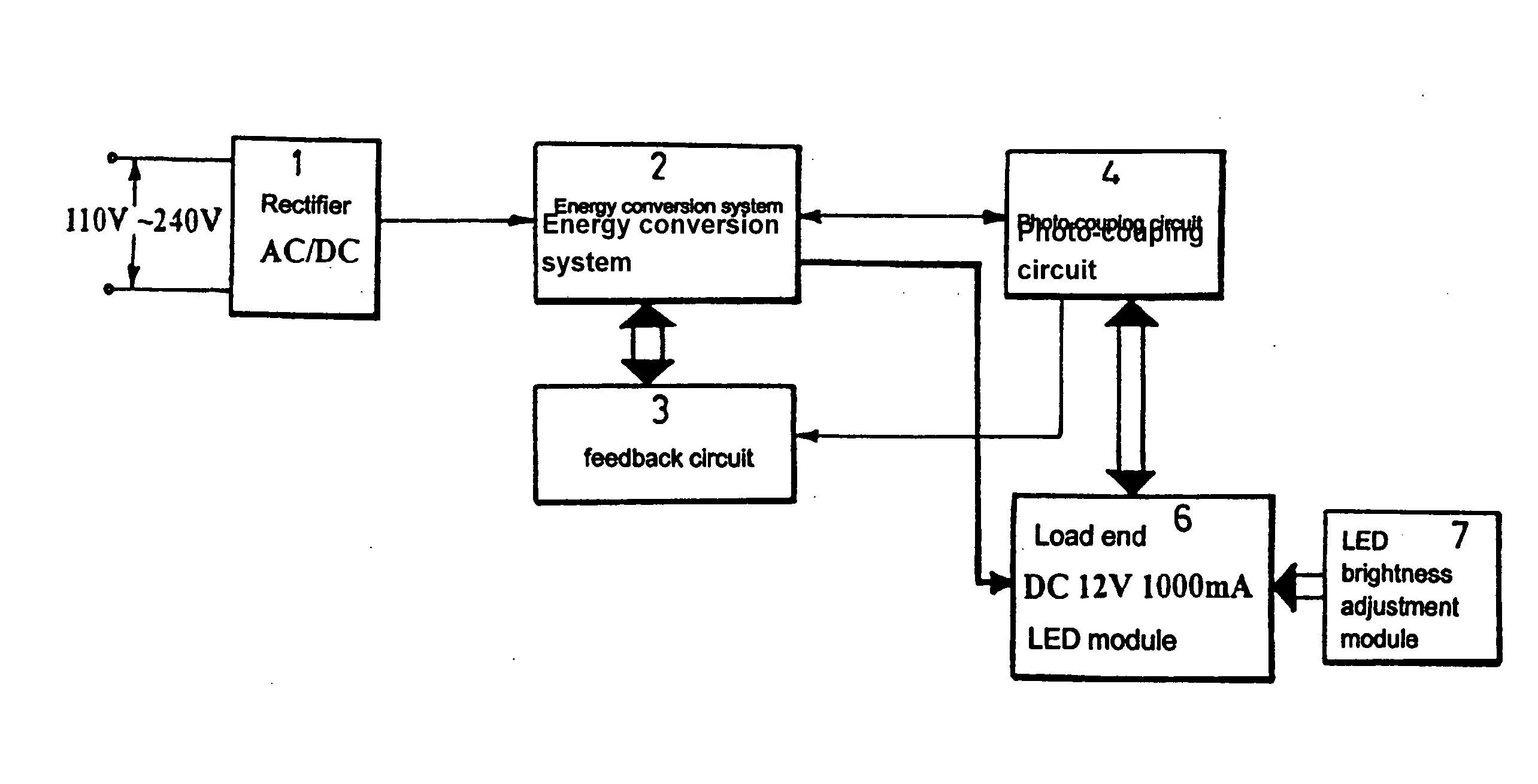
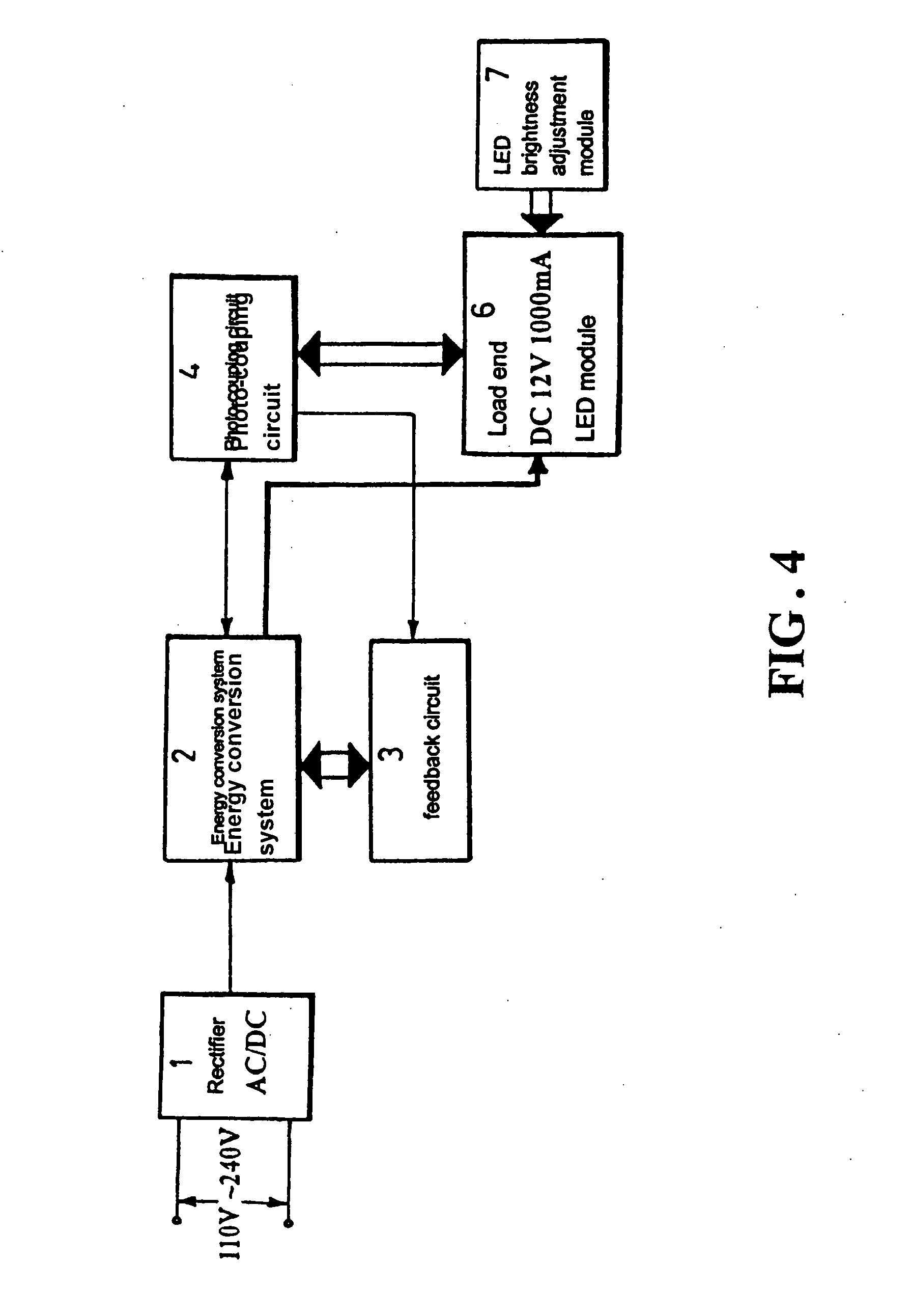
[0044]Further referring to FIGS. 4, 7, and 8, which show the present invention, on the basis of the previous circuit architecture, to make the brightness of the LED module 6 of the load end adjustable for enhancing the usability and controllability of the LED module 6, the LED module 6 of the load end is integrated with of an LED brightness adjustment module 7 to realize stepless adjustment of brightness. As shown in FIGS. 7 and 8, the LED brightness adjustment module 7 is constructed to employ the adjustment feature provided by voltage division resistors and a variable resistor 71 for controlling voltage applied to a gate of a power transistor 72 to thereby realize adjustment and control of the current through the load circuit of the light-emitting diode and further the instantaneous charging / discharging characteristics of capacitors is used to stabilize the variation of instantaneous current caused in the load end by the brightness adjustment of the variable resistor 71 to realize...

third embodiment

[0045]Based on the previously described architecture, further referring to FIGS. 5 and 6, which illustrate the present invention, to provide a solution to thermal problems of the circuit and the LED module 6 of the load end, and to provide effective protection, attempts of decreasing and / or increasing current and / or voltage are taken to effectively control the generation of heat. Thus, on the basis of the previously described circuit architecture, a system heat detection circuit 5 and a heat balance circuit 8 and a system heating module 9 are further provided. The system heat detection circuit 5 serves to overcome the problems of abnormal temperature increase of circuit caused by long-term operation, as well as satisfying requirements for outside appearance of products and safety regulation, which leads to unavailability of instantaneous removal of heat, potentially affecting conversion efficiency and life span of the power supply device. Further, the circuit 5 may provide effective...


PUM


Abstract

An electronic power supply device is provided for light-emitting diodes (LEDs), which employs electronic control to maintain the LEDs within the rated ranges of current, voltage and temperature and provides the LEDs with extremely stable current, voltage and temperature. Meanwhile, the power supply device is effective in confining the LEDs within the rated ranges of voltage, current, and temperature so that the excellent electronics protection and design of logic device realized by the power supply device effectively overcomes aging/deterioration of LEDs caused by exceeding voltage and current and burning out due to exceeding temperature and also effectively pushes the rated current and voltage of a (low-power) LED module toward the maximum values to provide the greatest luminous efficiency for upgrading the applications of the LEDs to the primary grade of lighting.

Description

BACKGROUND OF THE INVENTION[0001](a) Technical Field of the Invention[0002]The present invention relates to an electronic power supply device for light-emitting diodes (LEDs), which is aimed to provide an electronic power supply device for LEDs to make a breakthrough for the limitations imposed to the currently available (low-power) LEDs due to restriction and stability in voltage, current and temperature in order to make the application and lighting efficiency of the (low-power) LEDs well satisfying the general requirements for regular lighting purposes; thus the present invention is provided to enhance the lighting efficiency of the low-power LEDs by offering features of control, detection, protection, and brightness adjustment and maintaining stable effect of current, voltage and temperature within the rated ranges of voltage, current, and temperature to thereby improve the performance utilization efficiency of the whole LED module and make the low-power LEDs fully exploiting the...

Claims


Application Information

Patent Timeline
IPC IPC(8): G05F1/10
CPCH05B33/0815H05B33/0854Y02B20/341H05B45/12H05B45/18H05B47/28Y02B20/30H05B45/14H05B45/37
Inventor PAI, HAO-CHINCHEN, LI-TEHCHEN, SIANG-HSIUNGHSU, MIN-YUNG
Owner PAI HAO CHIN
Why Eureka
Try Eureka