Magnetic positioning for inductive coupling

Active Publication Date: 2009-08-27
PHILIPS IP VENTURES BV
View PDF67 Cites 258 Cited by
  • Summary
  • Abstract
  • Description
  • Claims
  • Application Information

AI Technical Summary

Benefits of technology

[0006]In a second aspect, the present invention provides a magnetic positioning system having a supplemental magnet to enhance the magnetic force of a principal magnet. In one embodiment, the supplemental magnet is positioned sufficiently close to the primary magnet to allow the magnetic field from the supplemental magnet to combine with and strengthen the magnetic field of the primary magnet. The primary magnet may be positioned within and subject to the full electromagnetic field, but be sufficiently non-conductive that it does not overheat. The supplemental magnet may be relatively conductive, but may be shielded so that it is subject t

Problems solved by technology

It may also limit the inductive power supply to use in connection with a single device specially configured to fit within the cup or cradle.
Although this reference discloses the use of a magnet for locating a light in the context of an inductive coupling, the sparse disclosure relating to magnets fails to address a number of issues.
First, the reference does not disclose where the magnets are located and whether

Method used


Image

  • Magnetic positioning for inductive coupling
  • Magnetic positioning for inductive coupling
  • Magnetic positioning for inductive coupling

Examples


Example

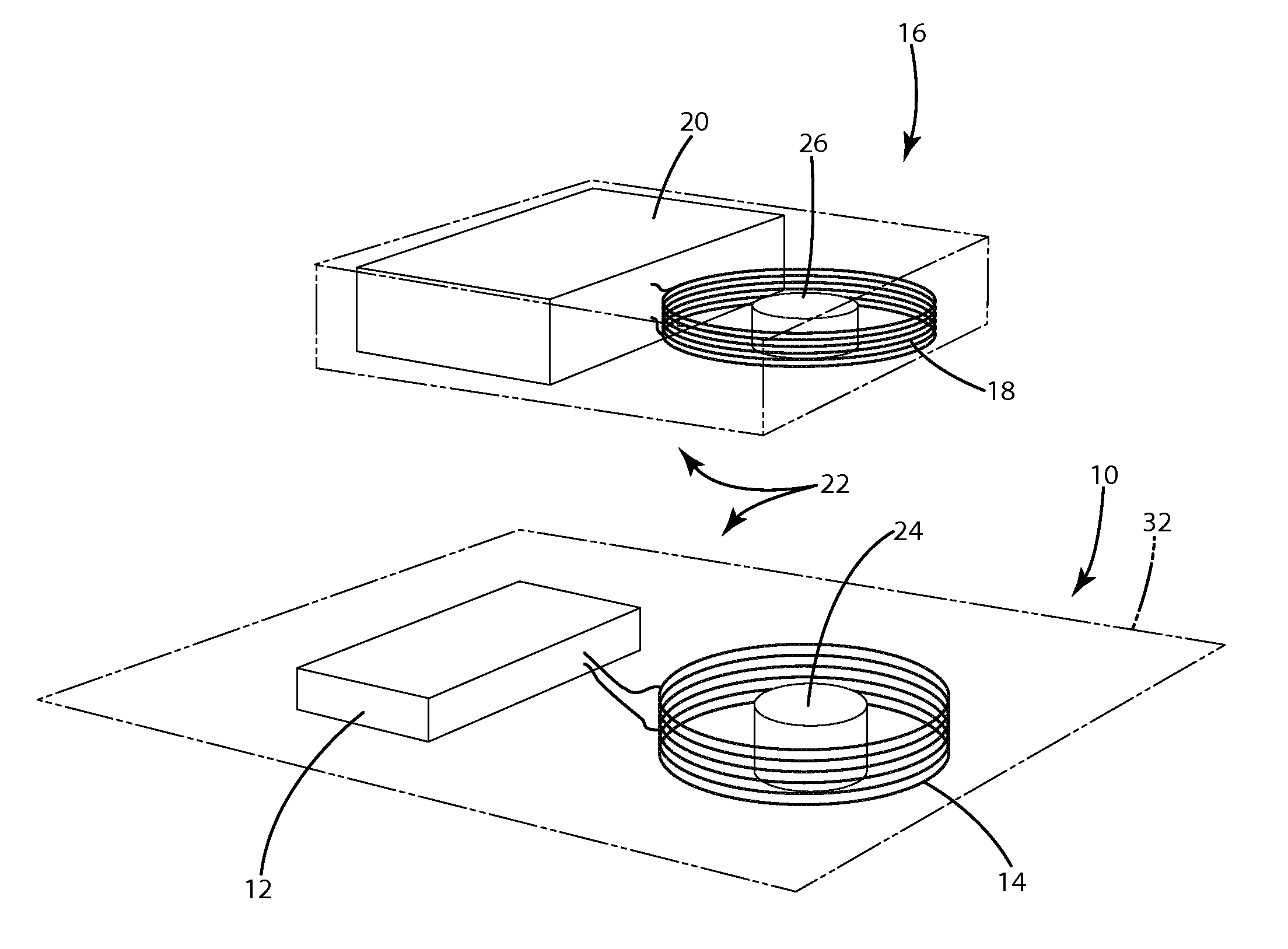
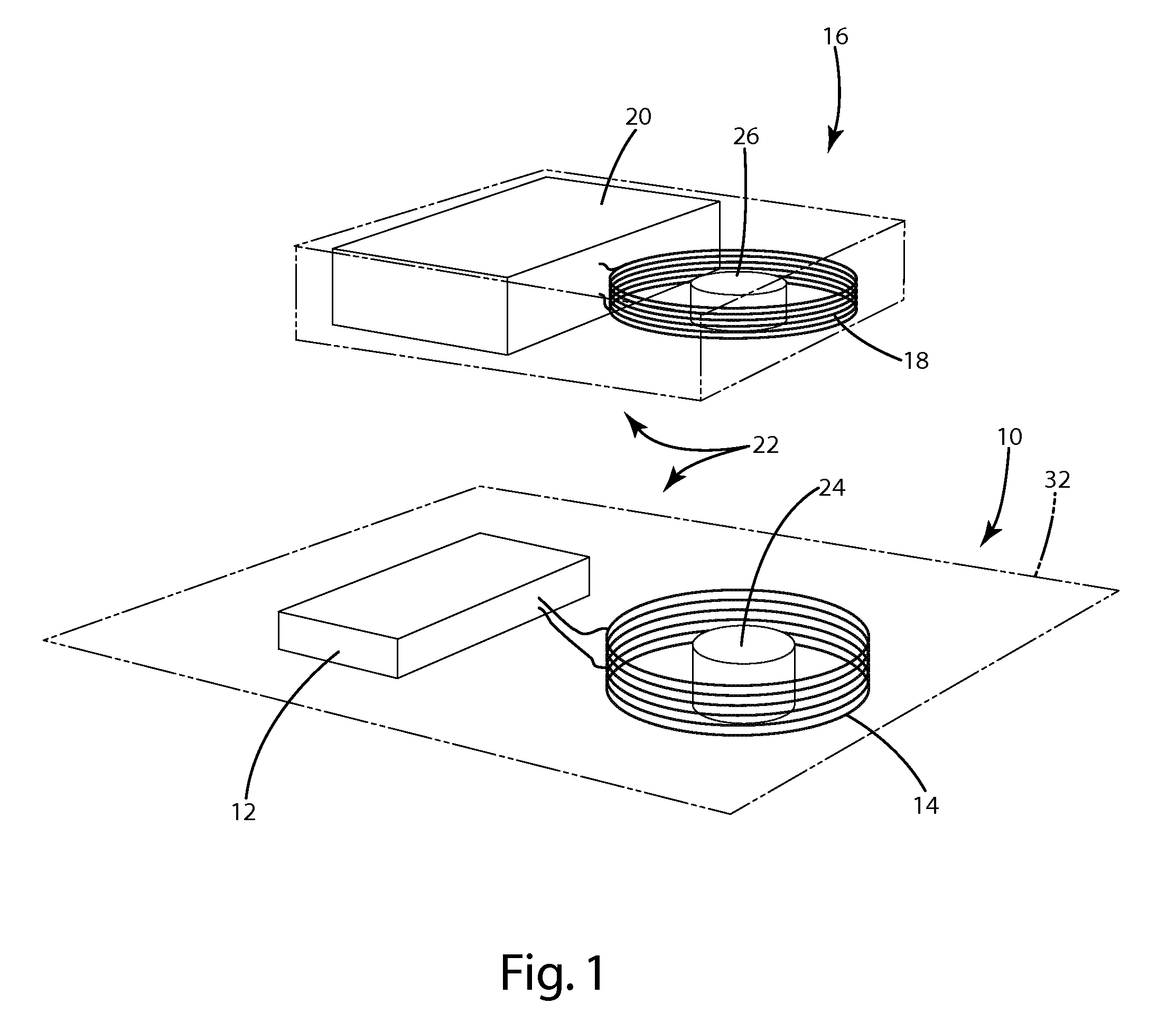
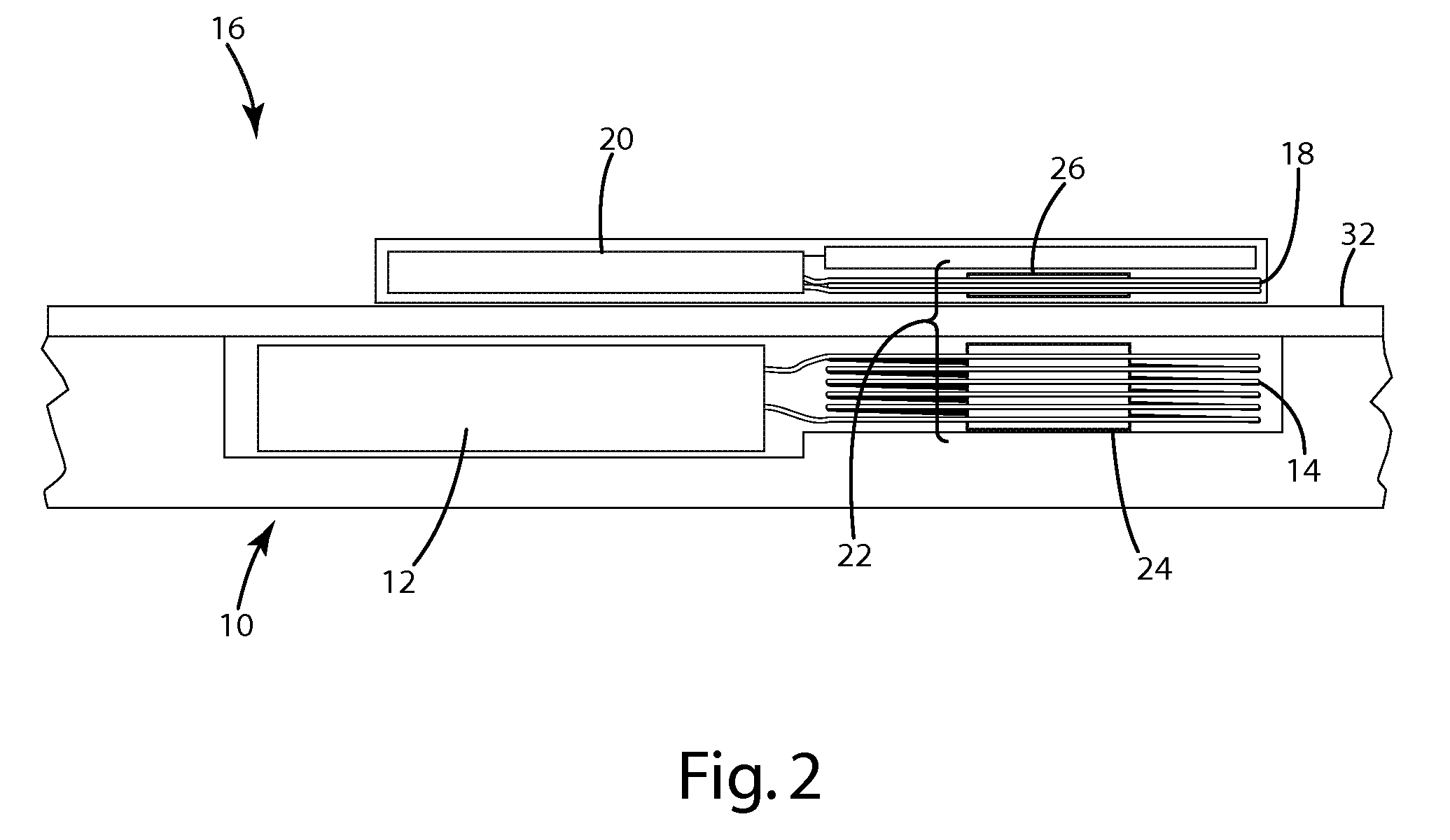
[0042]An inductive power supply and remote device incorporating a magnetic positioning system in accordance with the present invention are shown in FIG. 1. The inductive power supply 10 generally includes power supply circuitry 12 and a primary coil 14. The remote device 16 generally includes a secondary coil 18 and a load 20. The magnetic positioning system 22 generally includes a primary magnet 24 positioned in the approximate center of the primary coil 14 and a secondary magnet 26 positioned in the approximate center of the secondary coil 18. The two magnets 24 and 26 are oriented to attract one another and therefore assist in providing proper alignment between the power supply 10 and the remote device 16. The magnets 24 and 26 are sufficiently non-electrically conductive that they do not heat beyond acceptable limits in the presence of the electromagnetic field.

[0043]The present invention is suitable for use with essentially any inductive power supply. Accordingly, the inductive...


PUM


Abstract

A magnetic positioning system for use in inductive couplings. The magnetic positioning system having a magnet that provides sufficient magnetic force, but does not have enough electrical conductivity to overheat in the presence of the anticipated electromagnetic field. The magnet may be a bonded magnet or a shielded magnet. In another aspect a plurality of magnets are used to provide magnetic attraction forces and said magnetic repulsion forces that cooperate to align the inductive power supply and the remote device. In another aspect, a sensor allows differentiation between different positions of the remote device or inductive power supply. In another aspect, multiple magnets in the inductive power supply interact with multiple magnets in the remote device to position the remote device in different positions.

Description

[0001]This application claims the benefit of U.S. Provisional Application No. 61 / 030,586, filed Feb. 22, 2008.BACKGROUND OF THE INVENTION[0002]The present invention relates to inductive coupling and more particularly to systems and methods for positioning a device within an inductive field.[0003]With the advent of improved and less expensive electronics, there is a growing use of wireless power supply systems. Wireless power supply systems eliminate the need for cords and therefore eliminate the unsightly mess and the need to repeatedly connect and disconnect remote devices. Many conventional wireless power supply systems rely on inductive power transfer to convey electrical power without wires. A typical inductive power transfer system includes an inductive power supply that uses a primary coil to wirelessly convey energy in the form of a varying electromagnetic field and a remote device that uses a secondary coil to convert the energy in the electromagnetic field into electrical p...

Claims


Application Information

Patent Timeline
IPC IPC(8): H01F38/00
CPCH01F7/021H01F7/0247H04B5/0037H02J5/005H04B5/00H01F38/14H02J7/0042H02J50/90H02J50/70H02J50/10
Inventor BAARMAN, DAVID W.NORCONK, MATTHEW J.ZYLSTRA, BRAD A.
Owner PHILIPS IP VENTURES BV
Why Eureka
Try Eureka