

Mud retriever
- Summary
- Abstract
- Description
- Claims
- Application Information
AI Technical Summary
Benefits of technology
Problems solved by technology
Method used
Image

Examples
Embodiment Construction
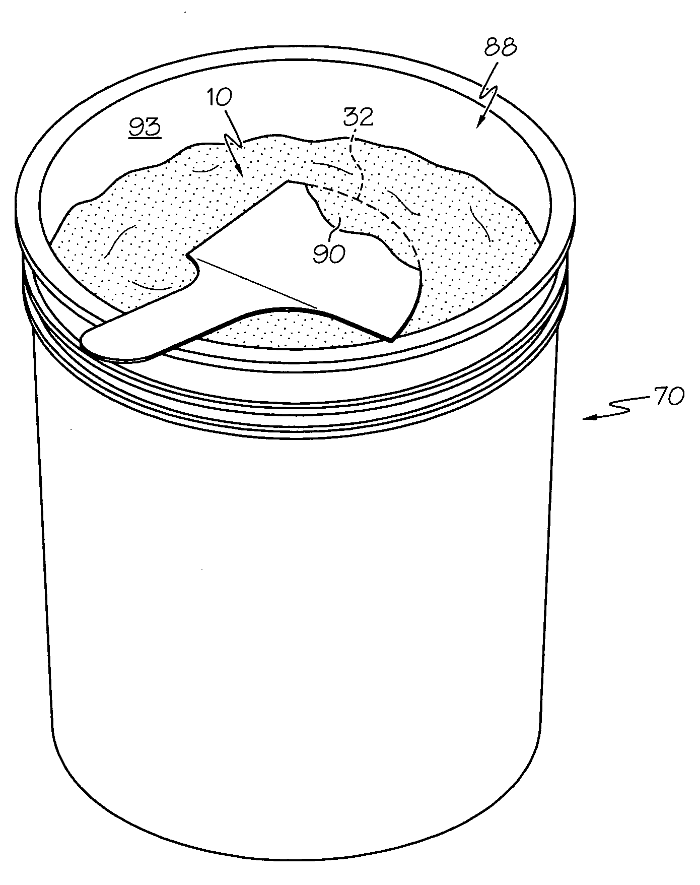
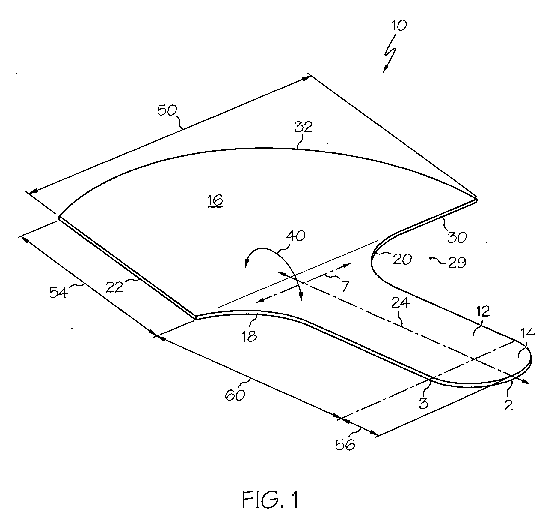
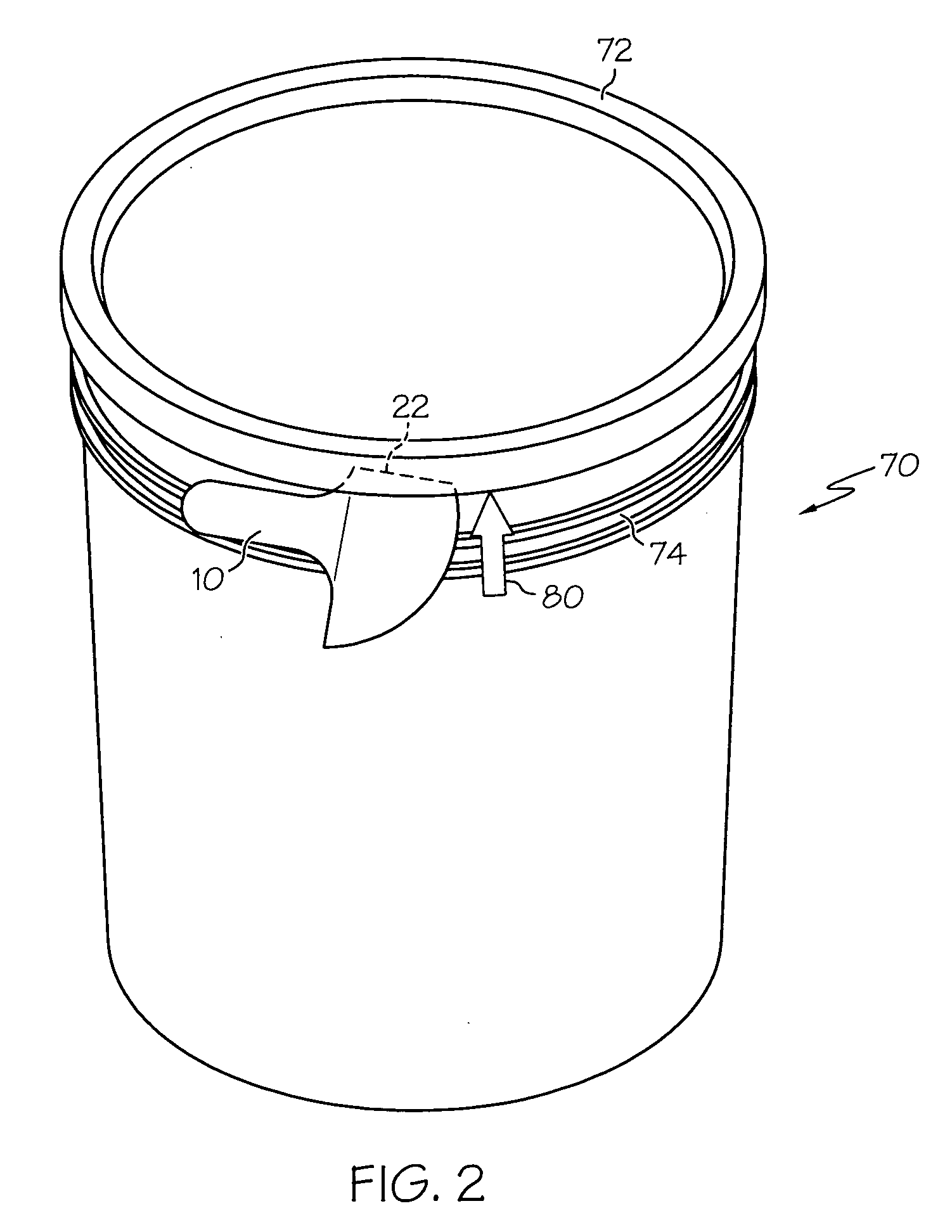
[0019]Referring now to FIG. 1, there is shown a mud retriever 10 which is made in accordance with the teachings of the preferred embodiment of the invention. It should be appreciated that the term “mud”, throughout this application, means drywall joint compound or some other type of substance which may be selectively retrieved from a container and applied in a desired manner. Thus, the present inventions are not limited to use with such drywall mud or any other specific type of material. Thus, retriever 10 may be used with substantially any type of material.
[0020]As shown, the mud retriever 10 includes a generally elongated handle portion 12 having a generally round or bulbous shaped bottom portion 14 and a blade portion 16 which integrally terminates into the handle portion 12 (e.g., the term “integrally terminates” means that the applicator 10 is, in the most preferred embodiment, formed as a “one piece” item).
[0021]Further, as shown, the handle portion 12 includes a pair of oppos...
PUM
 Abstract
Description
Claims
Application Information