Vehicle headlamp and method of controlling the same

Inactive Publication Date: 2009-09-17
KOITO MFG CO LTD
View PDF8 Cites 21 Cited by
  • Summary
  • Abstract
  • Description
  • Claims
  • Application Information

AI Technical Summary

Benefits of technology

[0011]Accordingly, illustrative aspects of the present invention provide a vehicle headlamp that can secure visibility of a driver and reduce glare caused to a front running vehicle.
[0012]According to an exemplary embodiment of the present invention, a vehicle headlamp is provided. The vehicle headlamp comprises a light source which is configured to form an additional light distribution pattern which is formed above a cut-off line of a low-beam mode light distribution pattern; a vehicle detection device which is configured to detect a presence of a front running vehicle; a road position detection device which is configured to detect an existing area of a road ahead; and a control unit which is configured to acquire informa

Problems solved by technology

Even though the high-beam mode is superior in visibility compared with the low-beam mode, there is a disadvantage in that the high-beam mode causes more glare light to a driver of a front running vehicle.
Accordingly, there is a disadvantage with the related art control technique in that a driver of the front running vehicle may falsely recognize that a following vehicle wants to pass.
However, there is a disadvantage in that when the following vehicle comes up on and encounters a front running vehicle before passing through a bent area of the curved road, th

Method used


Image

  • Vehicle headlamp and method of controlling the same
  • Vehicle headlamp and method of controlling the same
  • Vehicle headlamp and method of controlling the same

Examples


Example

[0022]Exemplary embodiments of the present invention will be now described with reference to the drawings.

[0023]The same or equivalent elements, members, and processes shown in the drawings are designated by the same reference numerals and repeated description thereof will be omitted.

[0024]In a vehicle headlamp according to an exemplary embodiment of the present invention, when an existing area of a road ahead includes an area where a vehicle ahead cannot be detected, an illuminance of an additional light distribution pattern which includes an upper area from a cut-off line of a low-beam mode light distribution pattern is reduced.

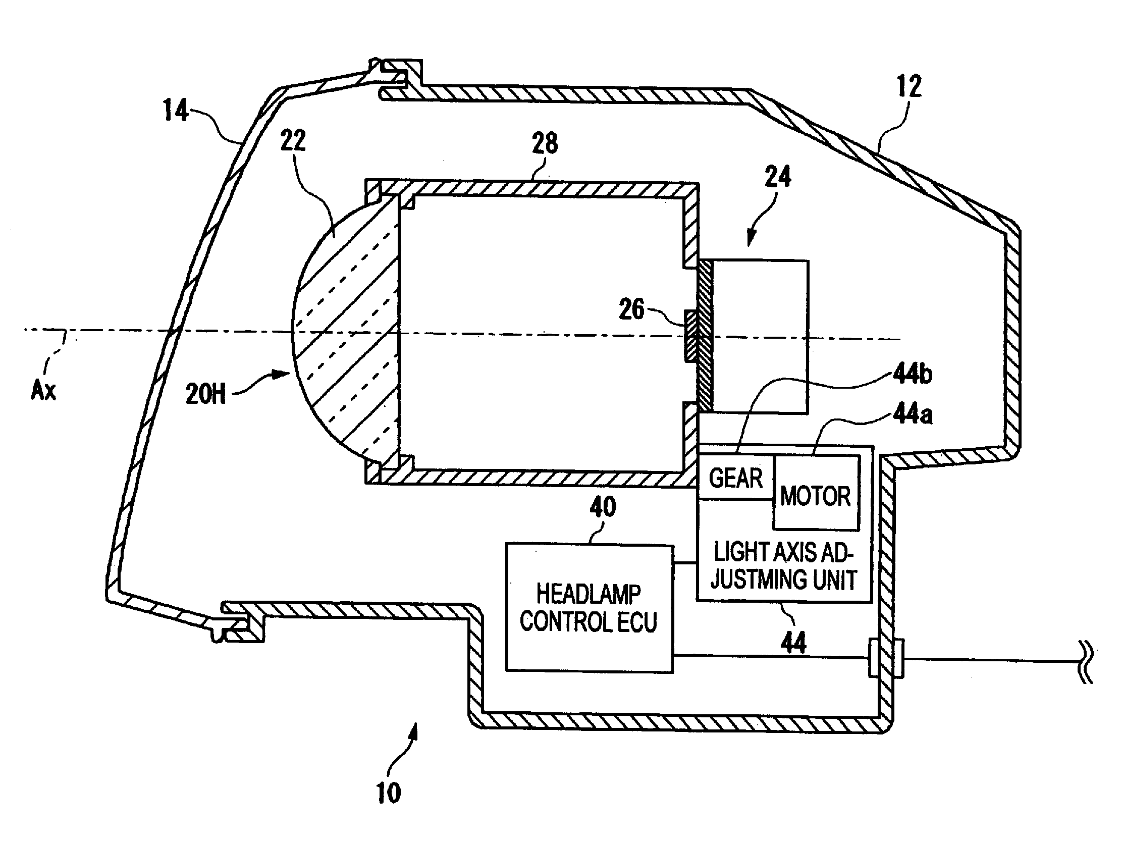
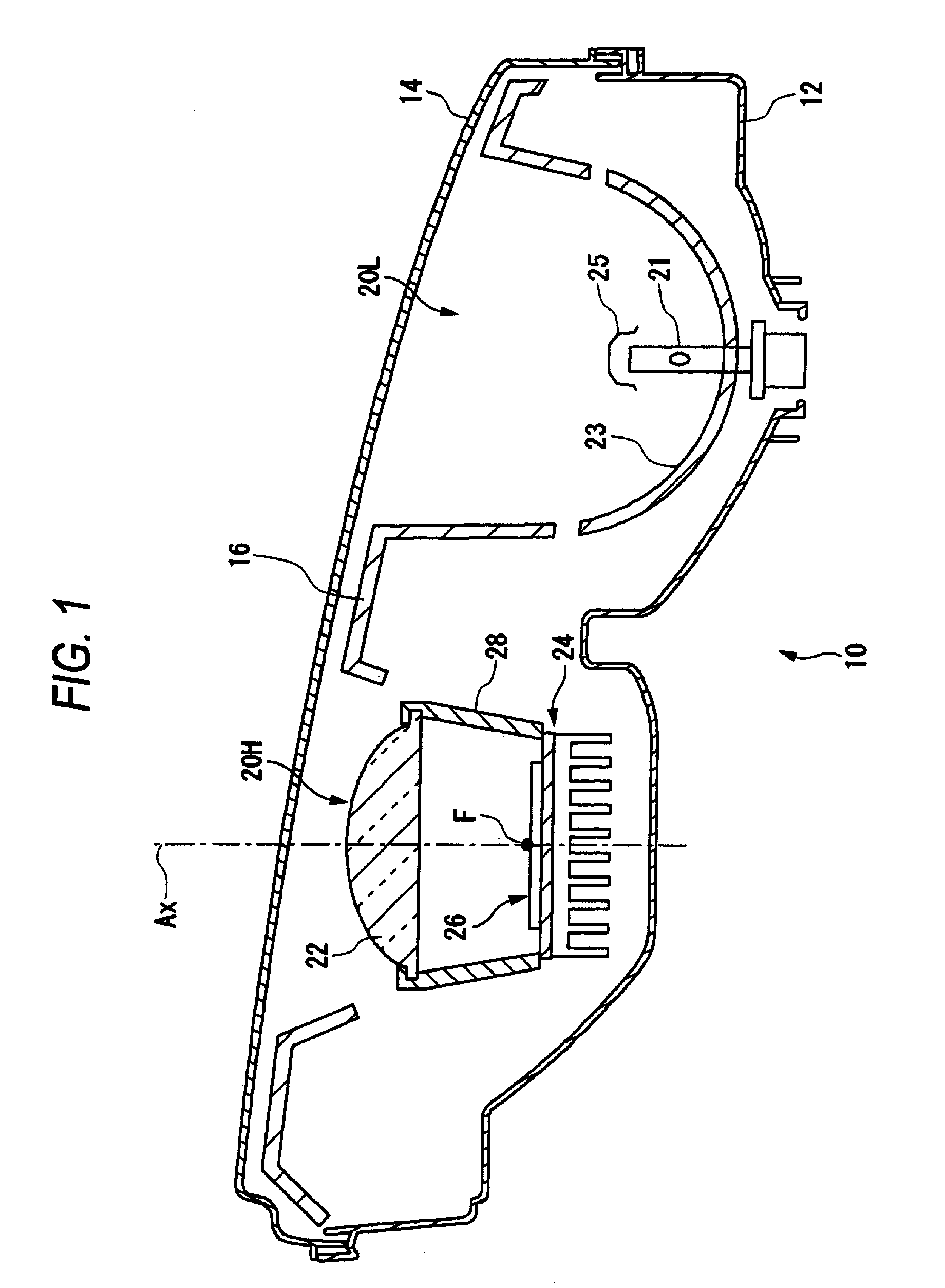
[0025]FIG. 1 is a horizontal sectional view schematically illustrating the vehicle headlamp according to an exemplary embodiment of the present invention.

[0026]The vehicle headlamp 10 according to accommodates a low-beam mode lamp 20L and a high-beam mode lamp 20H in an interior of a lamp housing which is formed by a lamp body 12 and a translucent cover 14....


PUM


Abstract

A vehicle headlamp is provided. The vehicle headlamp includes a light source which is configured to form an additional light distribution pattern which is formed above a cut-off line of a low-beam mode light distribution pattern; a vehicle detection device which is configured to detect a presence of a front running vehicle; a road position detection device which is configured to detect an existing area of a road ahead; and a control unit. The control unit acquires information from the vehicle detection device and the road position detection device and, when the existing area includes a non-detectable area which is outside of a detectable area of the vehicle detection device, controls the light source to reduce an illuminance of the additional light distribution pattern.

Description

[0001]This application claims priority from Japanese Patent Application No. 2008-0 62677, filed on Mar. 12, 2008, the entire contents of which are hereby incorporated by reference.BACKGROUND OF THE INVENTION[0002]1. Technical Field[0003]Devices, apparatuses, and methods consistent with the present disclosure relate to vehicle headlamps and, more particularly, to vehicle headlamps which control illuminance.[0004]2. Related Art[0005]In general, a vehicle headlamp provided on a vehicle can switch between a low-beam mode and a high-beam mode. The low-beam mode illuminates a place in the vicinity of a front running vehicle with a certain illuminance in order not to cause glare light to the front running vehicle. The front running vehicle includes an oncoming vehicle and / or a leading vehicle which travels in front of and in the same direction as the vehicle. The low-beam mode is mainly used when the vehicle runs in an urban district. On the other hand, the high-beam mode illuminates the f...

Claims


Application Information

Patent Timeline
IPC IPC(8): B60Q1/00
CPCB60Q1/143B60Q2300/054B60Q2300/056B60Q2300/42B60Q2300/122B60Q2300/322B60Q2300/336B60Q2300/112
Inventor MOCHIZUKI, KIYOTAKATATARA, NAOKI
Owner KOITO MFG CO LTD
Why Eureka
Try Eureka