Vehicle lighting device and lighting method

a technology for lighting devices and vehicles, applied in the direction of lighting support devices, lighting and heating devices, transportation and packaging, etc., can solve problems such as increasing the speed of vehicles

Active Publication Date: 2015-04-21
TOYOTA JIDOSHA KK
View PDF23 Cites 5 Cited by
  • Summary
  • Abstract
  • Description
  • Claims
  • Application Information

AI Technical Summary

Benefits of technology

[0008]The invention provides a vehicle lighting device and a vehicle lighting method of securing visibility when it is dark and prompting restraint of the vehicle speed on a dark occasion.
[0010]According to the foregoing construction, the light regions of reflection or emission of light darkens relative to other regions. Therefore, a vehicle driver will not misconceive that the entire field of view is visible, restraint of the vehicle speed can be prompted. Besides, visibility can be secured with respect to other regions. Therefore, visibility when it is dark can be secured, and restraint of the vehicle speed can be prompted.
[0014]The vehicle lighting device according to the foregoing aspect may further include specific determination means for specifically determining the light region that is apart from the vehicle by at least a predetermined distance, among the at least one light region detected by the detection means, and the control means may control the lighting means so that the light region specifically determined by the specific determination means has a dark light distribution relative to another region. This construction will prevent a misconception that the entire field of view is visible, and will prompt restraint of the vehicle speed, and will secure a certain recognizability of light regions with regard to areas near the host vehicle.
[0016]Besides, the vehicle lighting device according to the foregoing aspect may further include determination means for determining presence / absence of a travel impediment to the vehicle, and the control means may execute a control of the vehicle lighting means if it is determined by the determination means that the travel impediment is present. Due to this construction, since the light distribution control is performed according to the travel impediment characteristic, restraint of the vehicle speed will not be prompted more than necessary, and the achievement of both safety and comfort becomes possible. In the vehicle lighting device according to the foregoing aspect, the determination means may determine that the travel impediment is present, if at least one travel impediment that is at least one of a pedestrian and an obstacle is detected.
[0017]Besides, the vehicle lighting device according to the foregoing aspect may further include rain determination means for determining whether or not it is raining, and the control means may prohibit a control of the vehicle lighting means, if it is determined by the rain determination means that it is raining. According to the this construction, at the time of rain, the irregular reflection from the road surface increases, and therefore the visibility of a road surface shape or the like declines if there is a dark light distribution region. Therefore, by prohibiting the light distribution control during rain, visibility can be secured. Furthermore, the rain determination means may determine whether or not it is raining, based on state of operation of a windshield wiper of the vehicle.
[0018]Besides, in the vehicle lighting device according to the foregoing aspect, if it is determined by the rain determination means that it is raining, the control means controls the vehicle lighting means so that the light region detected by the detection means has a bright light distribution relative to another region on the road on which the vehicle travels. Due to the foregoing construction, visibility during rain can be secured, with priority given to the recognition of light regions, such as white lines, street lights, etc. during rain.

Problems solved by technology

In such a case, the vehicle driver, thinking that the visibility is good, may sometimes increase the vehicle speed.

Method used


Image

  • Vehicle lighting device and lighting method
  • Vehicle lighting device and lighting method
  • Vehicle lighting device and lighting method

Examples


first embodiment

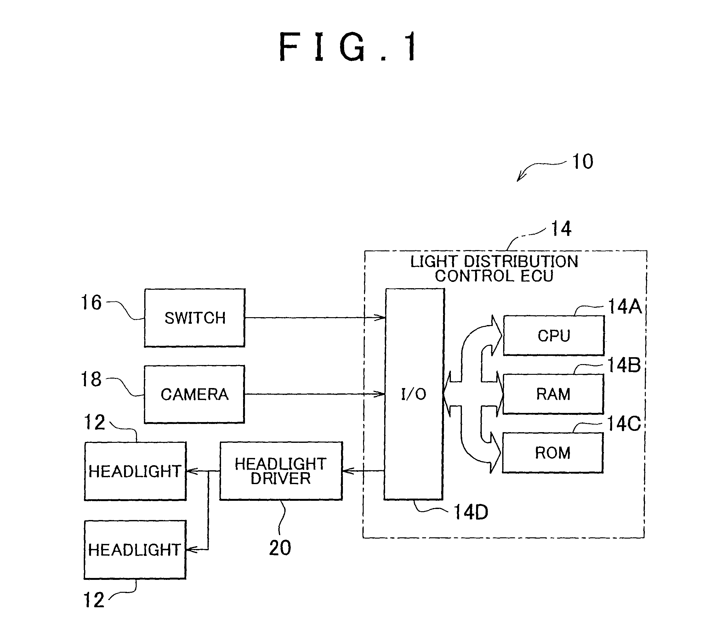
[0035]FIG. 1 is a block diagram showing a construction of a vehicle lighting device in accordance with the invention.

[0036]In a vehicle lighting device 10 shown in FIG. 1 in accordance with the first embodiment of the invention, headlights 12 (an example of vehicle lighting means in the invention) provided in a vehicle are connected to a light distribution control ECU 14 (an example of control means in the invention), so that the turning on and off of the headlights 12 is controlled by the light distribution control ECU 14.

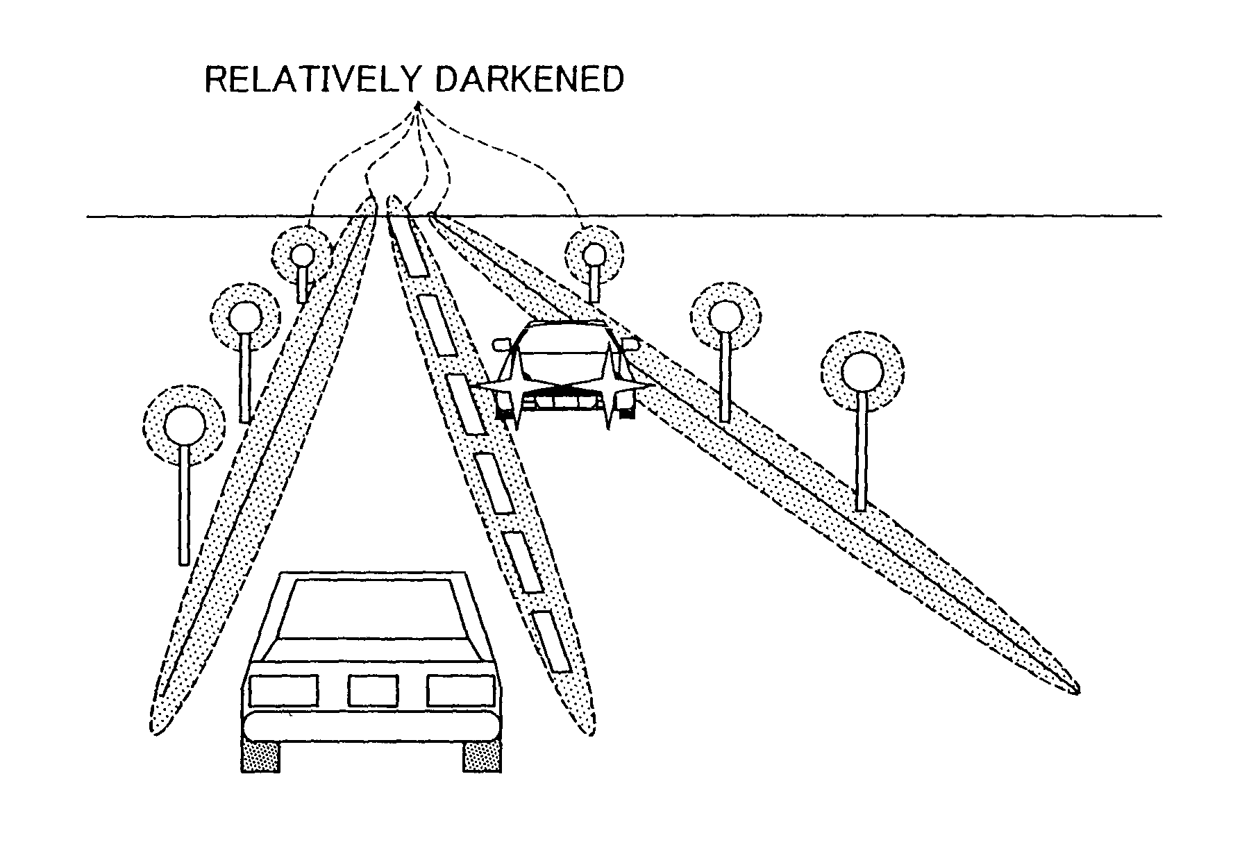
[0037]In this embodiment, the light distribution control ECU 14 controls the light distribution so that in a light distribution region irradiated by the headlights 12, at least one of a light region on a traveling road which reflects light and a light region on a traveling road which emits light has a relatively dark light distribution relative to regions other than the light-reflecting region and the light-emitting region on the traveling road. In addition, concr...

second embodiment

[0065]Subsequently, a vehicle lighting device in accordance with the invention will be described.

[0066]While in the first embodiment the light distribution control is performed so that the light reflection / emission regions have a relatively reduced amount of light relative to other regions in the light distribution region that is irradiated by the headlights 12 regardless of which one of the low beam and the high beam is selected, the second embodiment is constructed so as to perform the light distribution control only with respect to the high-beam region.

[0067]The construction of the vehicle lighting device in accordance with the second embodiment is basically the same as that in the first embodiment, and therefore only differences will be described with reference to FIG. 1.

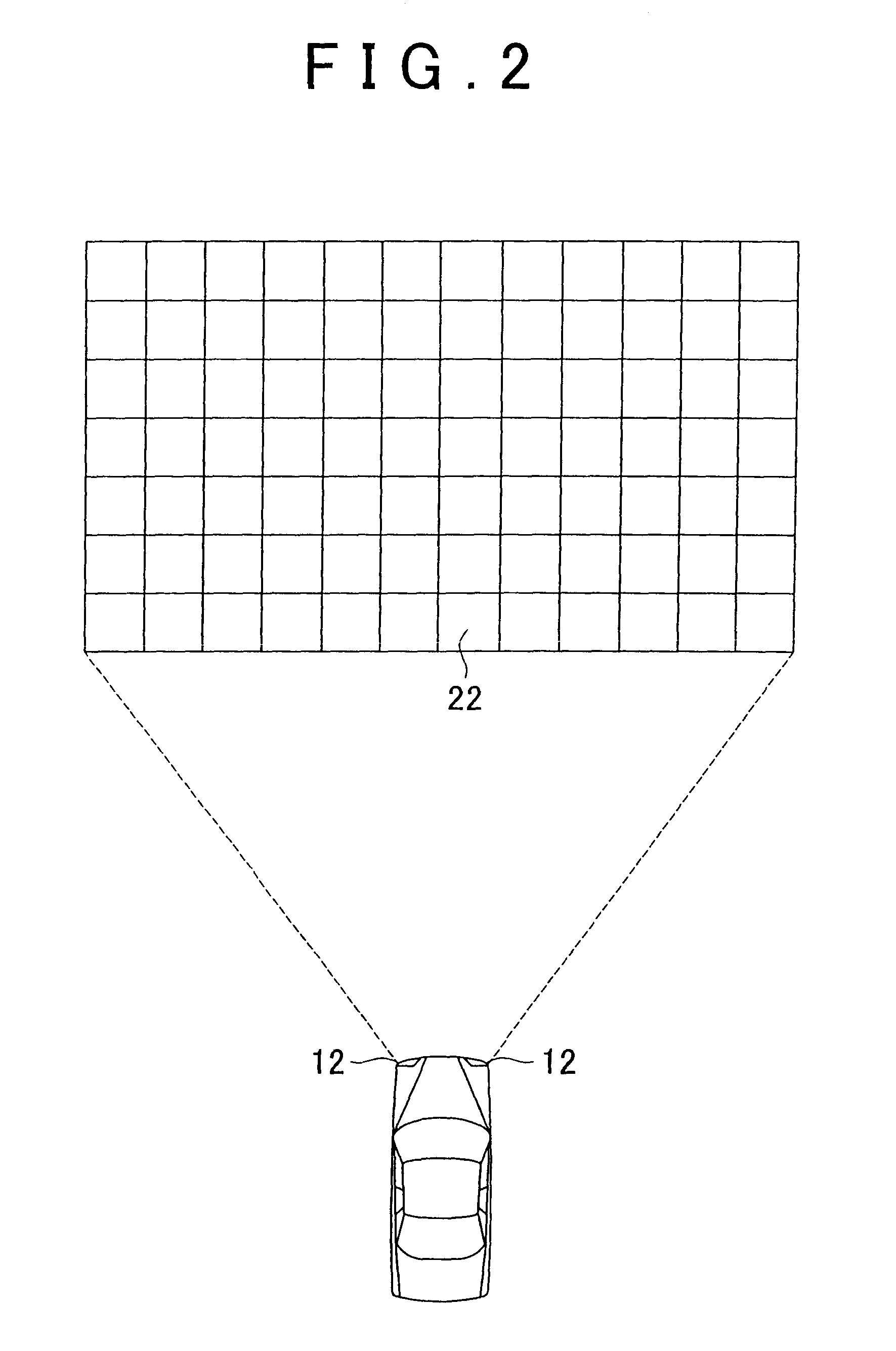
[0068]In the second embodiment, correspondence relations between the divided regions 22 and regions in shot images that correspond to a predetermined low-beam region and a high-beam region, respectively, are pre...

third embodiment

[0092]Furthermore, in the vehicle lighting device in accordance with the third embodiment, a vehicle speed sensor 40 is connected to the I / O 14D of the light distribution control ECU 14, and results of the detection of the vehicle speed performed by the vehicle speed sensor 40 are input to the light distribution control ECU 14.

[0093]In this embodiment, the braking distances for individual vehicle speeds for the time of rain and for the time of sunshine are predetermined in the ROM 14C of the light distribution control ECU 14, and positions in shot images that correspond to the braking distances and the divided regions that correspond thereto are determined and stored beforehand in the ROM 14C as well.

[0094]The light distribution control ECU 14 of this embodiment determines the braking distance, and performs the light distribution control described above in conjunction with the first embodiment only with respect to a region that is apart from the vehicle by the braking distance or mo...


PUM


Abstract

The light distribution region of headlights (12) is divided into a plurality of regions, and each of the divided regions can be irradiated or non-irradiated by light, and the light distribution characteristic can be changed separately for each divided region. The radiation or non-radiation of light to each divided region is controlled by a light distribution control ECU (14). Besides, light reflection / emission regions (hatched portions in FIG. 4) are detected by detecting light regions of reflection, such as white lines, reflectors, etc., and light regions of light emission, such as street lights or the like, are detected. Then, divided regions corresponding to light distribution region irradiated by the headlights (12) which correspond to the detected light reflection / emission regions are specifically determined, and the headlights (12) are controlled so that the light radiated to the specifically determined divided regions 22 becomes dark in light distribution relative to other regions.

Description

CROSS-REFERENCE TO RELATED APPLICATIONS[0001]This application is a national phase application of International Application No. PCT / IB2009 / 000380, filed Mar. 2, 2009, and claims the priority of Japanese Application No. 2008-062489, filed Mar. 12, 2008, the contents of both of which are incorporated herein by reference.BACKGROUND OF THE INVENTION[0002]1. Field of the Invention[0003]The invention relates to a lighting device and a lighting method for a vehicle. More particularly, the invention relates to a lighting device and a lighting method for a vehicle which control the light distribution of a headlight.[0004]2. Description of the Related Art[0005]Various related technologies of controlling the light distribution of a headlight of a vehicle in order to secure a forward visibility for the vehicle driver during nighttime travel.[0006]For example, a technology described in Japanese Patent Application Publication No. 2006-248246 (JP-A-2006-248246) includes lighting range control means...

Claims


Application Information

Patent Timeline
Patent Type & Authority Patents(United States)
IPC IPC(8): B60L1/14B60Q1/02B60Q1/08
CPCB60Q1/085B60Q2300/054B60Q2300/056B60Q2300/312B60Q2300/42B60Q2300/45F21S41/645
Inventor WATANABE, SHINYA
Owner TOYOTA JIDOSHA KK
Why Eureka
Try Eureka