Visibility adjusting method and apparatus of vehicle

a technology of adjusting method and apparatus, which is applied in the direction of windows, roofs, transportation and packaging, etc., can solve the problems of blocking the visibility of the passenger on the assistant driver's seat, reducing the amount of lightening within the vehicle, and blocking the visibility of the passenger. , to achieve the effect of stabilizing driving posture, suppressing inclination angle, and suppressing steering disturban

Active Publication Date: 2007-01-09
NISSAN MOTOR CO LTD
View PDF7 Cites 6 Cited by
  • Summary
  • Abstract
  • Description
  • Claims
  • Application Information

AI Technical Summary

Benefits of technology

[0008]According to the visibility adjusting method and apparatus according to the first aspect, since the visibility adjusting section has the lower visible light transmission than the windshield and does not completely shield the light entering into the vehicle, the driver and the passenger on the assistant driver's seat can see an outer side of the vehicle through the visibility adjusting section, and can take a suitable light into the vehicle. In other words, it is possible to improve a visibility near the vehicle at an extremely low speed range, increase an amount of lighting, and enlarge a visible range of the passenger on the assistant driver's seat.
[0010]According to the visibility adjusting method and apparatus of the vehicle according to the second aspect, since the parting line which blocks the forward visibility and is inclined to the right and left sides is applied to the lower end of the windshield, it is possible to suppress a sway of a head inclination angle by stabilizing a balance sense of the driver, and it is possible to suppress a steering disturbance based on a stability of a driving posture. Further, according to the visibility adjusting method and apparatus of the vehicle according to the present invention, since at least one of the right and left ridgelines is separated into two or more ridgelines which are approximately parallel to each other and are arranged in different levels, it is possible to uniformize the angle of the ridgeline forming the parting line applied to the driver while limiting the area of the visibility adjusting section to be small, and thus it is possible to achieve both of an effect of stabilizing the driving posture and an effect of securing the visibility during medium and low speed running.

Problems solved by technology

In such a conventional visibility adjusting method of a vehicle, however, since it is made such that a forward visibility by the driver is adjusted by shielding a lower end of the windshield, the visibility near the vehicle is blocked at the time when the vehicle runs at an extremely low speed range such as the time of backing the vehicle in to a garage, the time of passing closely-by and the like, whereby there is a case that the driver feels insecure.
Further, in the conventional visibility adjusting method of a vehicle, since it is made such that the forward visibility by the driver is adjusted by shielding the lower end of the windshield, an amount of lightening within the vehicle is reduced, and the visibility of the passenger on the assistant driver's seat is blocked, whereby there is a case that the passenger on the assistant driver's seat is annoyed.

Method used


Image

  • Visibility adjusting method and apparatus of vehicle
  • Visibility adjusting method and apparatus of vehicle
  • Visibility adjusting method and apparatus of vehicle

Examples


first embodiment

[0046]A visibility adjusting method according to a first embodiment of the invention will be explained first.

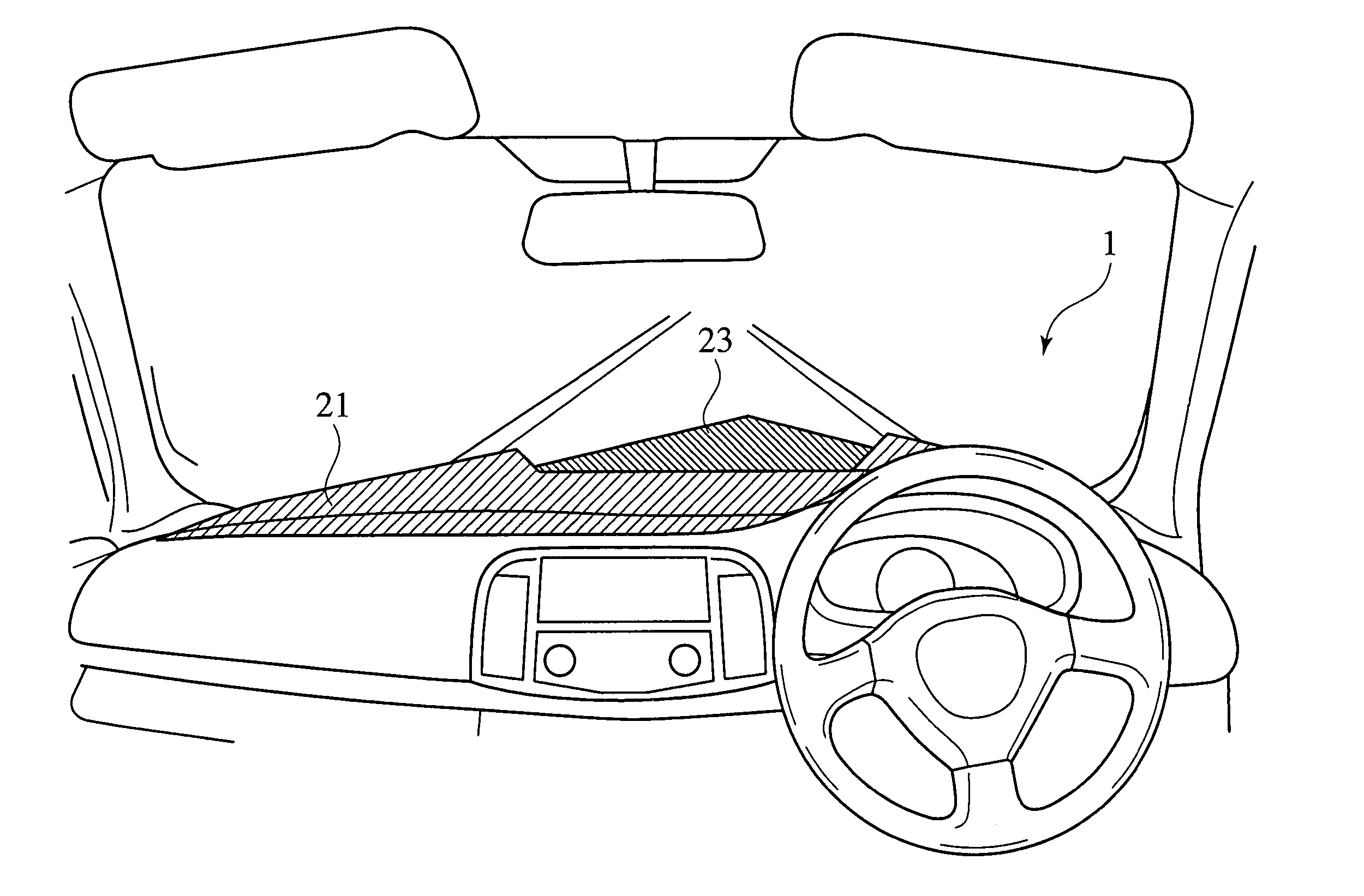
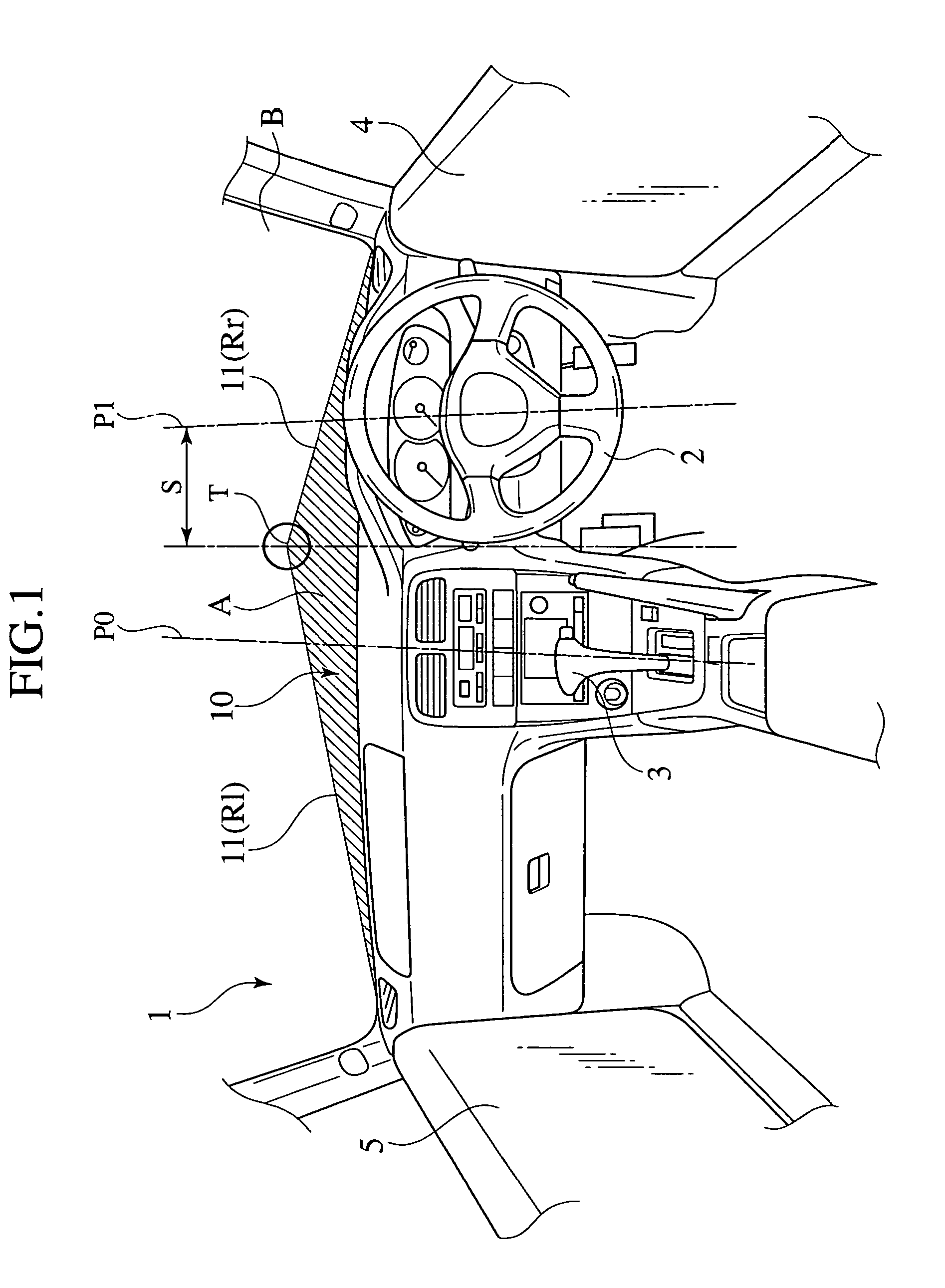
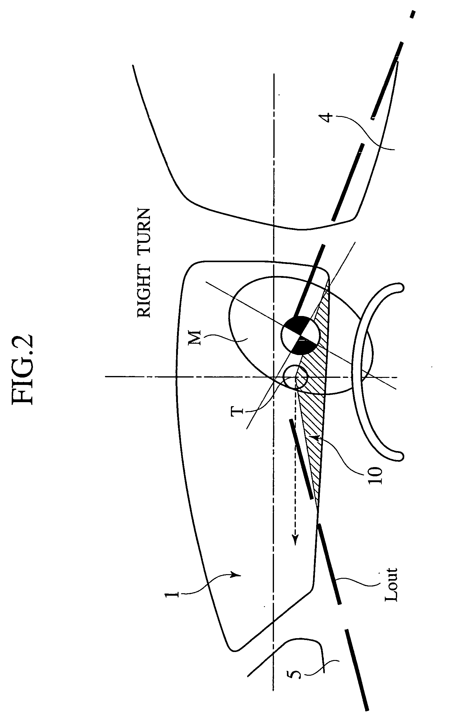
[0047]A visibility adjusting method according to a first embodiment is, as shown in FIG. 1, such that a visibility adjusting section 10 is provided in a lower end of a windshield 1 and a forward visibility by a driver is adjusted by the visibility adjusting section 10. Further, the visibility adjusting section 10 is formed by (1) disposing an apex T at a position which is between an opposing position P1 to the driver and a vehicle center position P0 and is deviated from the opposing position P1 to the driver at a distance S, (2) setting left and right ridgelines Rl and Rr which are uniformly inclined from the apex T toward opposite sides in a vehicle-width direction, (3) making a visible light transmission of an area A which is in a lower side of the left and right ridgelines Rl and Rr lower than a visible light transmission in an area B which is in an upper side thereof and ...

second embodiment

[0059]Next, a visibility adjusting method according to a second embodiment of the invention will be explained.

[0060]The visibility adjusting method according to the second embodiment is, as shown in FIG. 10, such that the visible light transmission of the area A in the lower side of the left and right ridgelines Rl and Rr is intermittently and continuously changed such as a top shade of the windshield used for reducing glare of the passenger. In this case, in general, the top shade is provided in the upper end of the windshield, and is configured such as to uniformly increase the visible light transmission toward the passenger, however, in the present invention, it is not necessary to set the direction of changing the visible light transmission as the top shade.

[0061]In this case, it is desirable that the visible light transmission of the area A is, as shown in FIG. 10, such that the visible light transmission in the lowermost end is highest. With the configuration mentioned above, ...

third embodiment

[0069]Next, a visibility adjusting method of a vehicle according to a third embodiment of the invention will be explained.

[0070]The visibility adjusting method of a vehicle according to the third embodiment is, as shown in FIG. 24, such that the left ridgeline Rl is divided into two ridgelines including a first ridgeline Rl1 and a second ridgeline Rl2, and the first ridgeline Rl1 and the second ridgeline Rl2 are arranged approximately parallel to each other and in different levels, in the visibility adjusting method of a vehicle according to the first embodiment. In this case, in FIG. 24, reference numerals 2, 3, 4 and 5 respectively denote a steering wheel, a control lever, a right front door and a left front door.

[0071]As mentioned above, in the visibility adjusting method of a vehicle according to the third embodiment, since the left ridgeline Rl is divided into two ridgelines including the first ridgeline Rl1 and the second ridgeline Rl2, and an area of the visibility adjusting ...


PUM


Abstract

A visibility adjusting section (10) is formed by making a visible light transmission of a region (A) in a lower side of left and right ridgelines (Rl, Rr) lower than a visible light transmission of a region (B) in an upper side of the left and right ridgelines (Rl, Rr). Accordingly, a driver and a passenger on an assistant driver's seat can see an outer side of a vehicle through the visibility adjusting section (10), and a suitable light can be taken into the vehicle. Further, since a parting line (11) of the visibility adjusting section (10) is uniformly inclined downward toward opposite sides in a vehicle-width direction from an apex (T) disposed at a position which is deviated from a driver, a driving posture of the driver is stabilized, and it is possible to suppress a disturbance in a steering operation.

Description

BACKGROUND OF THE INVENTION[0001]The present invention relates to a visibility adjusting method and an apparatus for adjusting a driver's forward visibility by providing a lower end of a windshield with a visibility adjusting section, and more particularly to a technique for achieving an improvement of a visibility near the vehicle at an extremely low speed range, an increase of an amount of lighting within a vehicle and an enlargement of a visible range by a passenger on an assistant driver's seat.[0002]Conventionally, there is known a visibility adjusting method of a vehicle in which a lower end of a windshield is shielded, and the forward visibility of a driver is adjusted, thereby enhancing the safety as disclosed in Japanese Patent Application Laid-Open No. 2000-211355 for example.[0003]In such a conventional visibility adjusting method of a vehicle, however, since it is made such that a forward visibility by the driver is adjusted by shielding a lower end of the windshield, th...

Claims


Application Information

Patent Timeline
Patent Type & Authority Patents(United States)
IPC IPC(8): B60J1/00B60J3/00B60J3/04
CPCB60J3/04
Inventor ITO, MITSUHITOUENUMA, KENYAIWAO, KEIJIRO
Owner NISSAN MOTOR CO LTD
Why Eureka
Try Eureka