Radiofrequency or hyperfrequency circulator

a radiofrequency or hyperfrequency circulator technology, applied in the direction of coupling devices, electrical equipment, waveguide type devices, etc., can solve the problems of radiofrequency circulators used, ferromagnetic circulators, serious malfunctions or even destruction of these components, etc., to reduce production costs, simplify the design of circulators, the effect of occupied surface area and electrical power dissipation

Active Publication Date: 2009-09-24
THALES SA
View PDF19 Cites 16 Cited by
  • Summary
  • Abstract
  • Description
  • Claims
  • Application Information

AI Technical Summary

Benefits of technology

[0012]The invention provides an alternative solution allowing the design of the circulators to be simplified, their production cost, the surface area occupied and the electrical power dissipated to be reduced.

Problems solved by technology

The reason for this is that any signal arriving on the output of the HPA could lead to a serious malfunctioning or even the destruction of this component.
According to the prior art, the radiofrequency circulators used are bulky structures using a ferrite and a permanent magnet that impose a direction of electromagnetic gyration.
However, these ferromagnetic circulators have various drawbacks.
They are very costly components.
They are not easily reproducible, since they require human intervention for correct adjustment.
Their structure is very bulky.
They consume a large amount of electrical power, and consequently pose problems of thermal dissipation.

Method used


Image

  • Radiofrequency or hyperfrequency circulator
  • Radiofrequency or hyperfrequency circulator
  • Radiofrequency or hyperfrequency circulator

Examples


Embodiment Construction

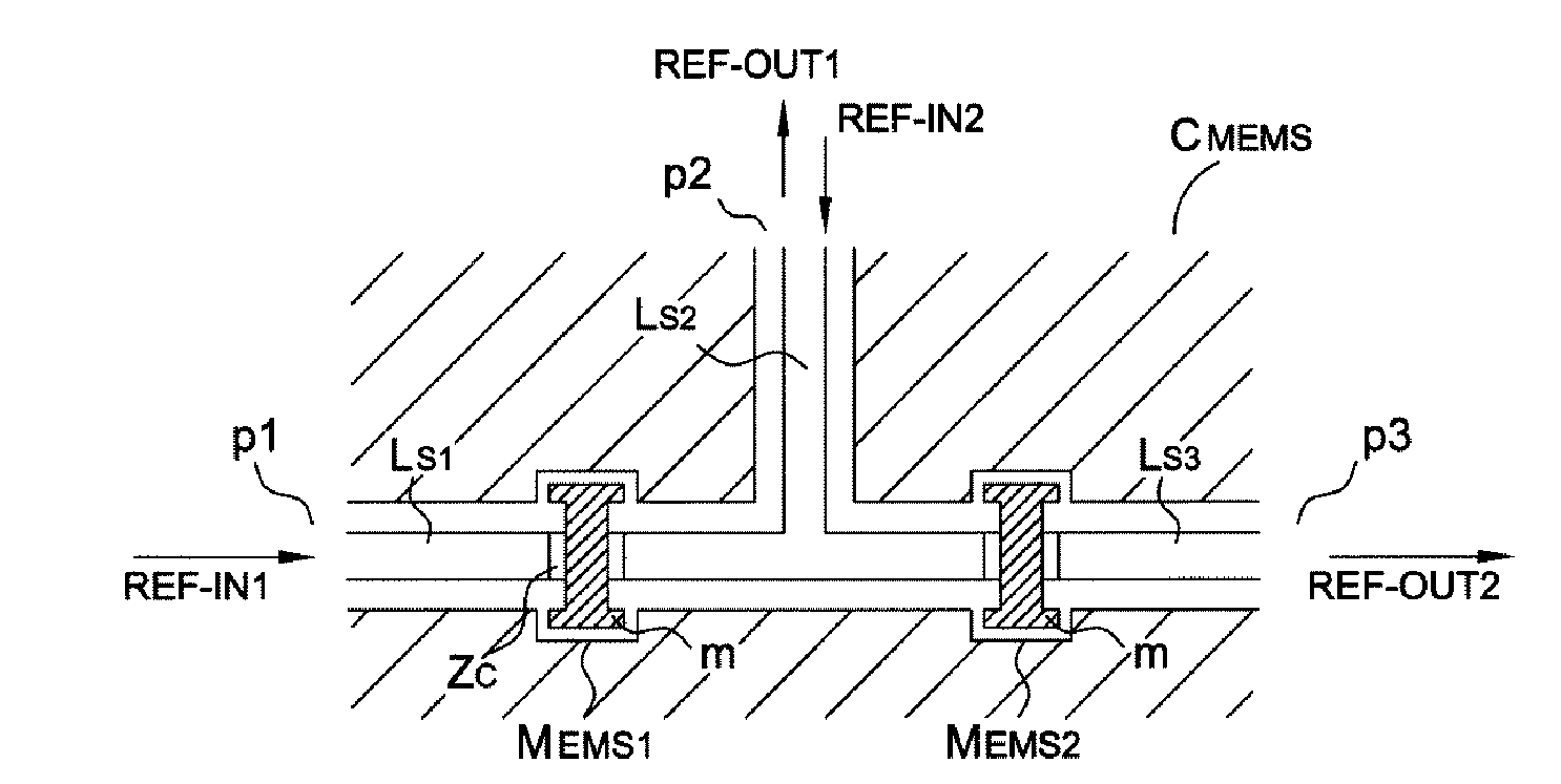
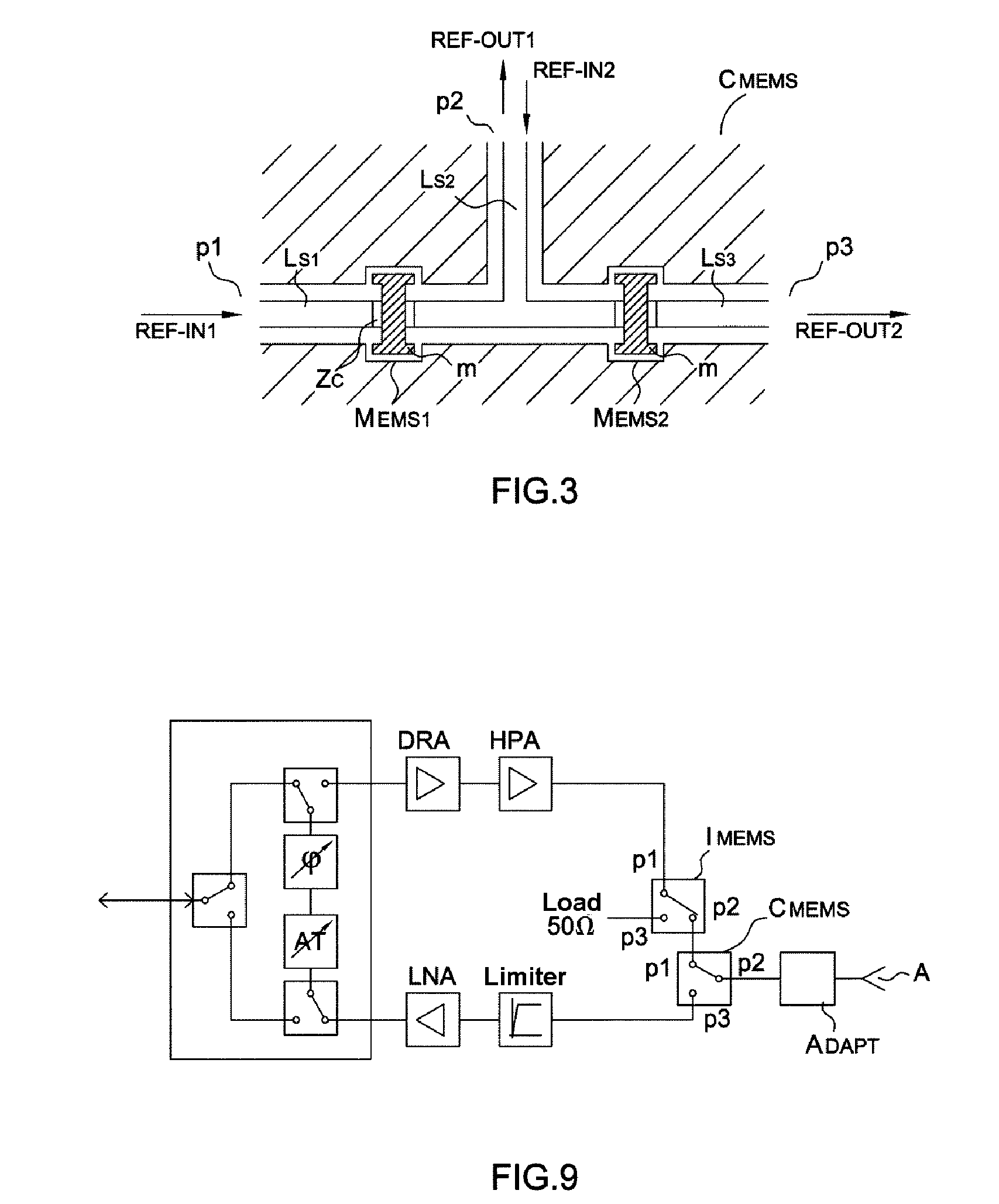
[0041]A circulator CMEMS according to the invention is described with reference to FIGS. 3 to 9. As illustrated in FIG. 3, the circulator CMEMS comprises two identical micro-switches of the series type. A first micro-switch MEMS1 is disposed in order to allow the transmission of a radiofrequency or microwave signal from an input port p1 via a signal line Ls1 to a port p2 designed to be connected to an antenna, via a second signal line Ls2. A second micro-switch MEMS2 is disposed in order to allow the signal transmission from the second port p2, via the signal line Ls2 to an output port p3, via a third signal line Ls3.

[0042]The entire circulator, notably with the micro-switches and the signal lines, is formed on the same base substrate.

[0043]Generally speaking, each micro-switch of the series type comprises an assembly membrane—dielectric material—control electrode that forms a variable capacitor for which the membrane and the electrode form the plates. The control electrode is dispo...


PUM


Abstract

A circulator with at least three ports (p1, p2, p3) comprises two identical electromechanical micro-switches of the series type (MEMS1, MEMS2) formed on the same substrate, a first micro-switch being disposed in order to allow the transmission of a radiofrequency or microwave signal from an input port (p1) to a port (p2) designed to be connected to an antenna, a second micro-switch being disposed in order to allow the signal transmission between the port (p2) designed to be connected to an antenna and said output port. Application to a radiofrequency or microwave telecommunications system.

Description

CROSS-REFERENCE TO RELATED APPLICATIONS[0001]The present Application is based on International Application No. PCT / EP2007 / 055355, filed on May 31, 2007, which in turn corresponds to French Application No. 0604857 filed on May 31, 2006, and priority is hereby claimed under 35 USC § 119 based on these applications. Each of these applications are hereby incorporated by reference in their entirety into the present application.FIELD OF THE INVENTION[0002]The field of the invention is that of radiofrequency RF circulators and of their applications in radiofrequency or microwave telecommunications systems such as radar or wireless telephony systems.[0003]An RF circulator is a device with n ports, allowing an RF signal to flow in only one direction. A circulator with three ports p1, p2, p3 is considered. A signal injected into a port p1 is transmitted to the port p2 and isolated from the port p3, whereas a signal input via the port p2 is transmitted to the port p3 and isolated from the port...

Claims


Application Information

Patent Timeline
Patent Type & Authority Applications(United States)
IPC IPC(8): H01P1/38
CPCH01H59/0009H01P1/38H01P1/127
Inventor ZIAEI, AFSHIN
Owner THALES SA
Why Eureka
Try Eureka