Sternal clamp with rib extension

Inactive Publication Date: 2009-10-01
TEAGUE MIKE +3
View PDF4 Cites 169 Cited by
  • Summary
  • Abstract
  • Description
  • Claims
  • Application Information

AI Technical Summary

Problems solved by technology

In certain circumstances, the strength and rigidity of the sternum may be insufficient to withstand the compressive forces of the sternal clamp, such t

Method used


Image

  • Sternal clamp with rib extension
  • Sternal clamp with rib extension
  • Sternal clamp with rib extension

Examples


Embodiment Construction

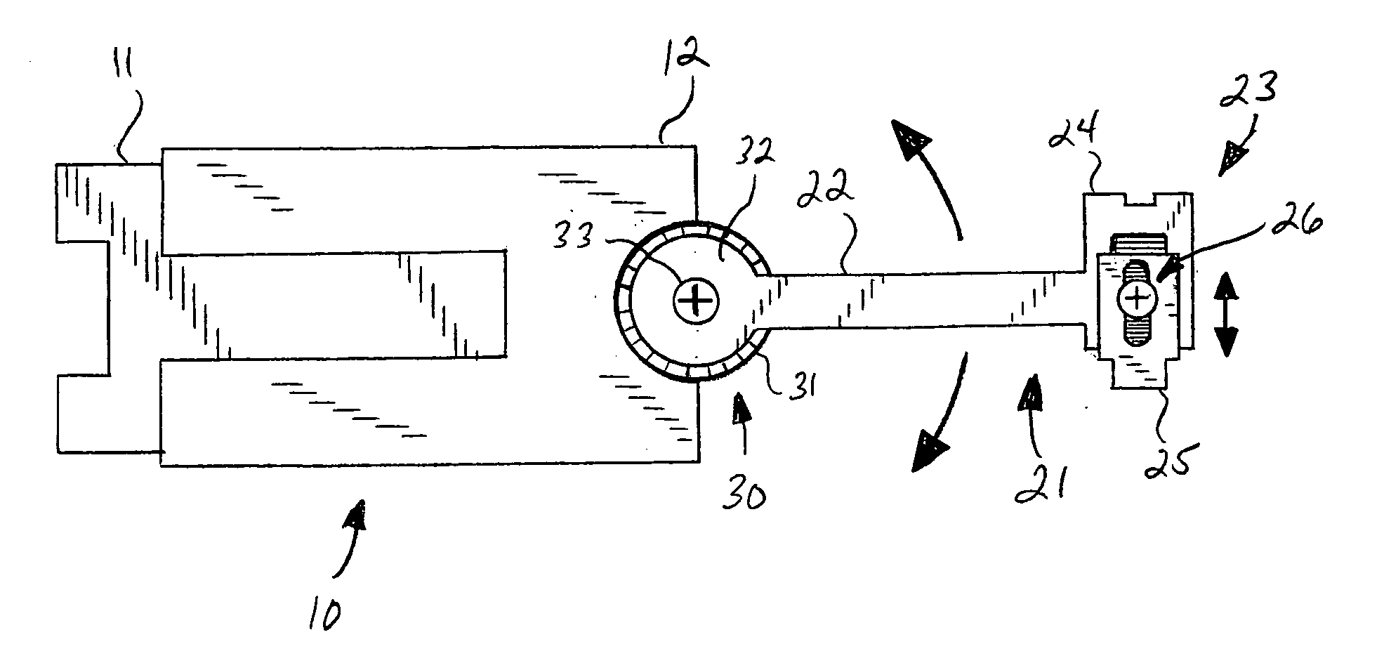
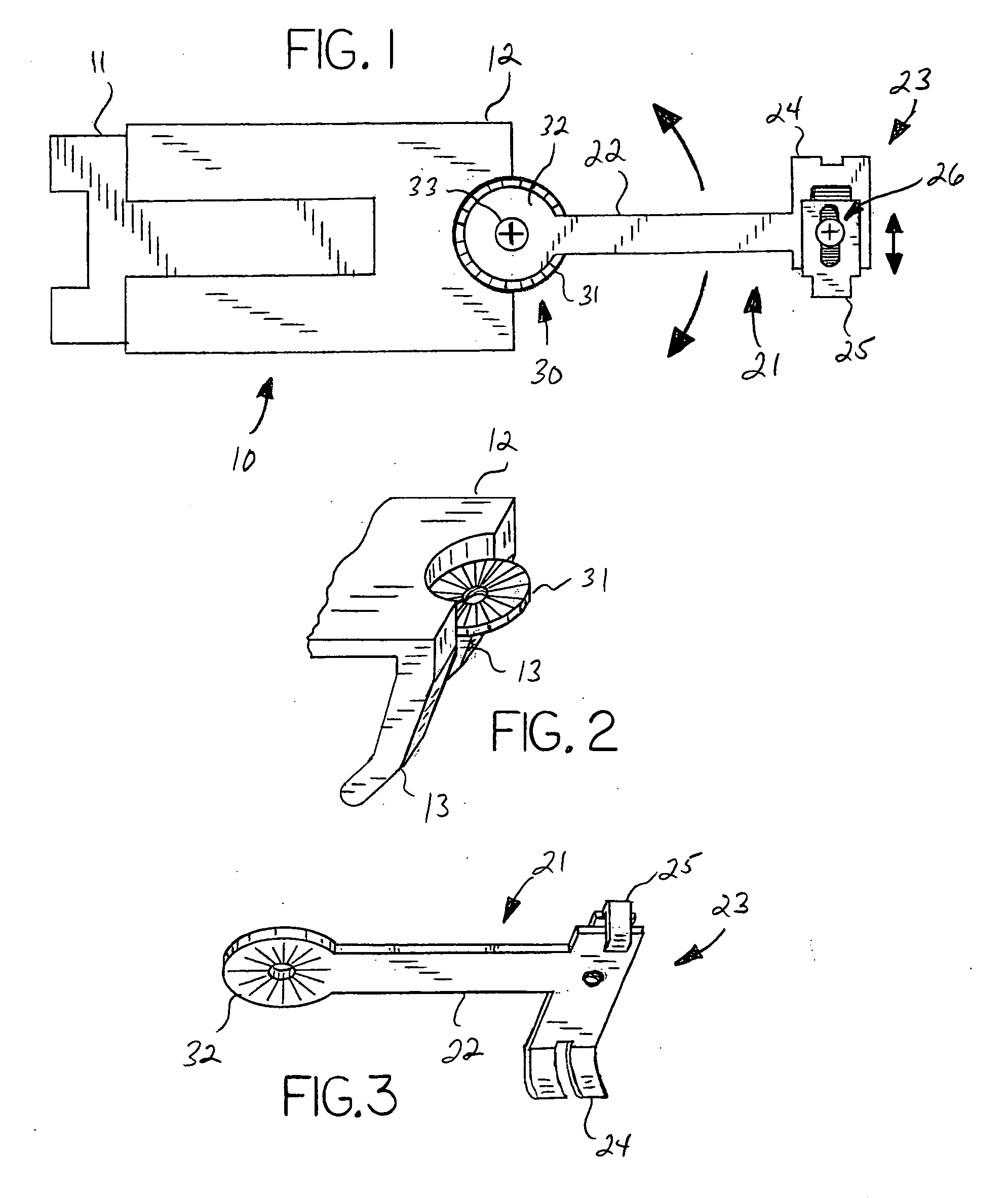
[0014]With reference to the drawings, the invention will now be described in detail with regard for the best mode and the preferred embodiment. The invention is a sternal closure clamp device used to close, secure and support a sternum post-operatively, the sternum having been severed longitudinally into left and right lateral sternal halves to provide access to the interior of the chest, wherein the sternal clamp comprises two opposing body members and a rib extension member mounted to at least one of said body members.

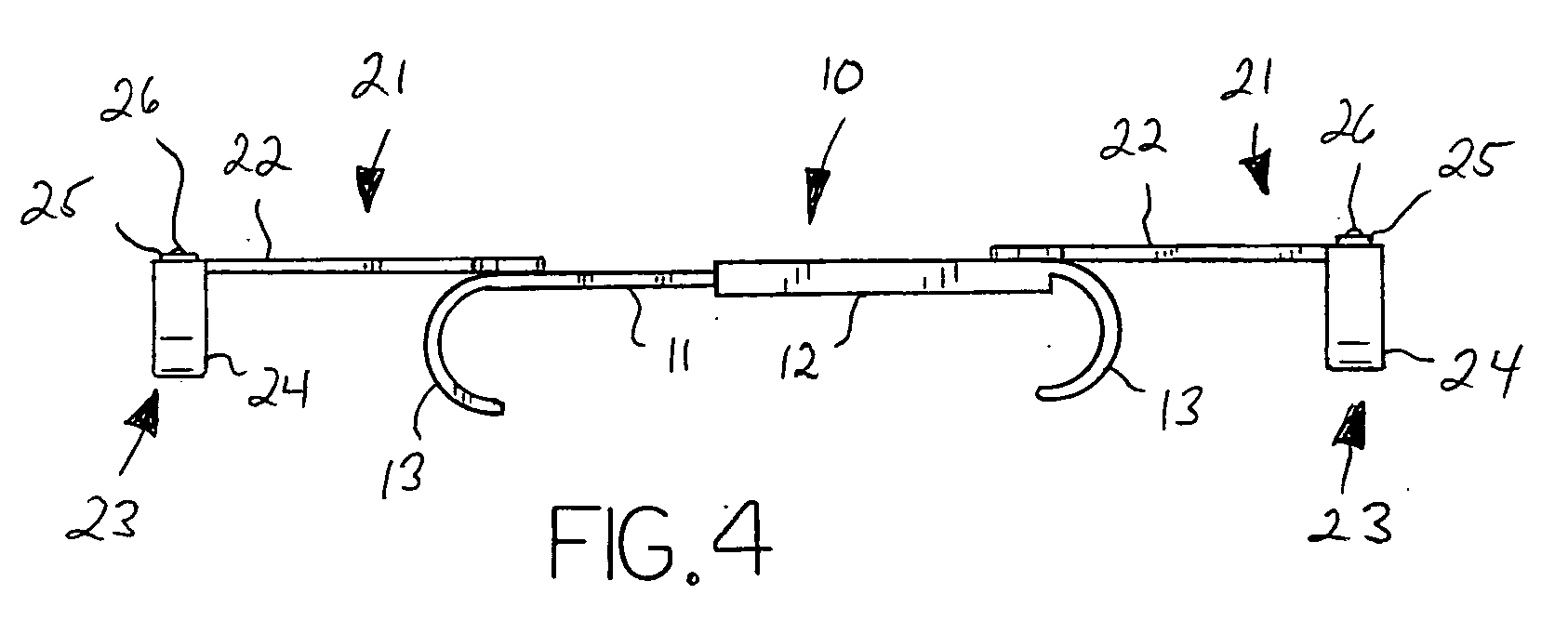
[0015]The sternal clamp 10 generally comprises two opposing body members 11 and 12 each at least one and preferably a pair of spaced, sternum-engaging engagement members 13 extending posteriorly from the body members 11 and 12. The body members 11 and 12 are slidingly or telescopically interconnected such that the overall length of the sternal clamp 10 can be adjusted. The engagement members 13 are means to engage, secure or otherwise retain the sternal halves in an ...


PUM


Abstract

A sternal closure clamp device for securing and retaining longitudinally divided halves of a sternum, the device having a pair of body members each having engagement members adapted to abut the sides of the sternal halves, and at least one rib extension member having rib retaining means attached to at least one of said body members, such that the rib extension member can be secured to a rib to reduce the force being applied directly to the sternal halves.

Description

[0001]This application claims the benefit of U.S. Provisional Patent Application Ser. No. 61 / 069,982, filed Mar. 19, 2008.BACKGROUND OF THE INVENTION[0002]This invention generally relates to devices used to rejoin a human sternum that has been severed longitudinally, and more particularly relates to such devices that function in a clamping manner to retain the severed sternum portions in a closed and abutting relationship post-operatively.[0003]It is often necessary in surgical operations to longitudinally sever the patient's sternum so that the ribs may be spread to provide access to internal organs such as the heart. It is then necessary to secure the sternum halves together for post-operative recovery. Various closure techniques are used to accomplish this task. For example, holes may be drilled into the sternum halves and suture material passed through and tightened to cinch the sternum halves together. Apertured plates may be added to further rigidify the sternum post-operative...

Claims


Application Information

Patent Timeline
IPC IPC(8): A61B17/84
CPCA61B17/823
Inventor TEAGUE, MIKEANDERSON, CHARLESBURKE, SHAWNWALZENEGGER, AXEL
Owner TEAGUE MIKE
Why Eureka
Try Eureka