Breakaway lanyard and hardware for making same

Inactive Publication Date: 2009-10-15
1602211 ONTARIO
View PDF31 Cites 15 Cited by
  • Summary
  • Abstract
  • Description
  • Claims
  • Application Information

AI Technical Summary

Benefits of technology

[0028]Other advantages, features and characteristics of the present invention, as well as methods of operation and functions of the related elements of the structure, and the combination of parts and economies of man

Problems solved by technology

For example, it is possible for the lanyard strap or for the carrier structure to become caught on another object and result in constriction of the neck of the user.
This can result in minor to serious injury to the user, or even death.
This results in additional cost and inconvenience to the user.
Moreover, the lanyard would be rendered useless in situations wherein the user did not possess a replacement lanyard strap.
Furthermore, the necessity of carrying replacement lanyard straps is, in and of itself, an inconvenience to the user.
Designs of this latter type require the use of one or more additional pieces of lanyard strap and one or more lanyard strap connectors, with a corresponding increase in material and / or assembly costs.
Moreover, the point at which the segments are joined can be bulky and cumbersome, and may irritate the neck of user by contact therewith, particularly upon application of force to the lanyard lanyard strap prior to release.

Method used


Image

  • Breakaway lanyard and hardware for making same
  • Breakaway lanyard and hardware for making same
  • Breakaway lanyard and hardware for making same

Examples


Embodiment Construction

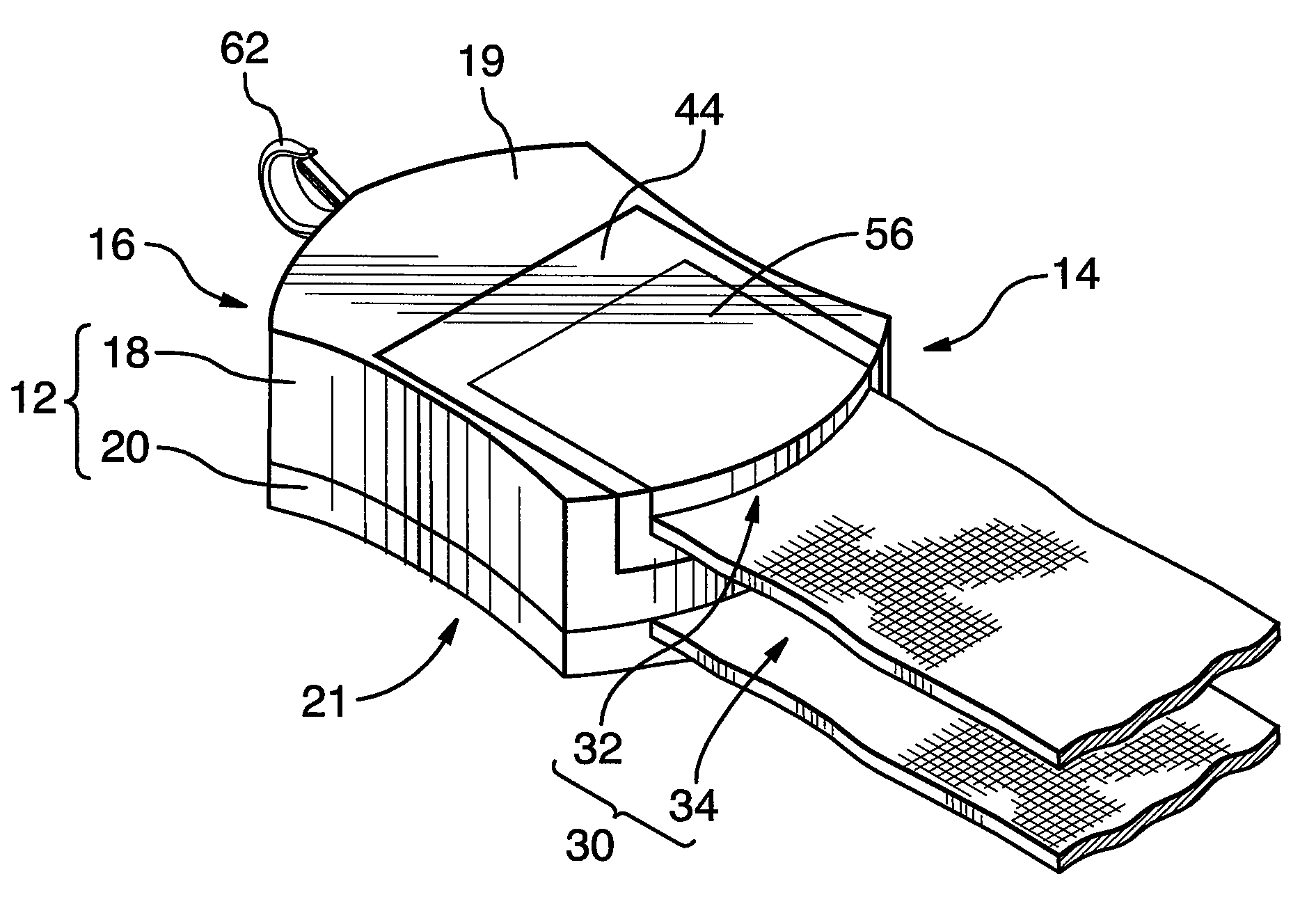
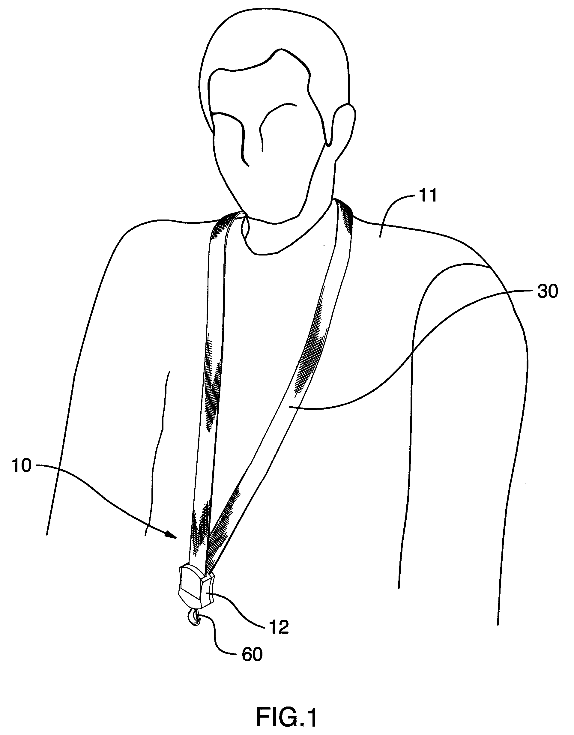
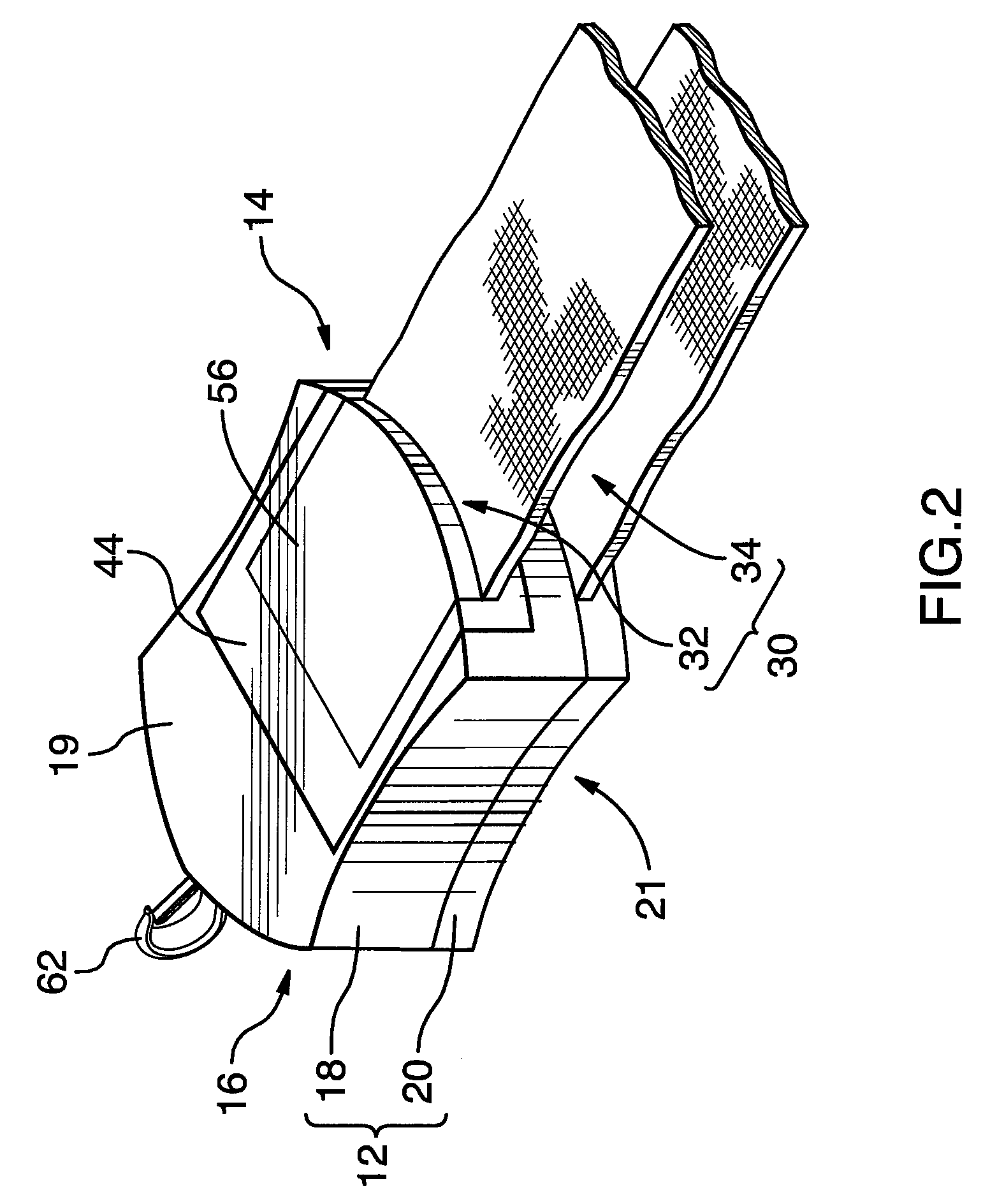
[0039]Referring now to FIG. 1, there will be seen a breakaway lanyard 10 comprising a carrier body 12 and a lanyard strap 30. The lanyard strap 30 may be worn about the neck of a user 11. Looking to FIG. 2, the carrier body 12 has an upper end 14 and an opposed lower end 16, and the lanyard strap 30 has a first end 32 and a second end 34.

[0040]The carrier body 12 includes a plurality of carrier body segments, preferably a front segment 18 and a rear segment 20 as shown in FIGS. 2, 3 and 4. The body segments 18, 20 are preferably formed from a plastic material and are engagable with one another, preferably by way of releasable snap-fit engagement. To enable such snap-fit engagement, the rear segment 20 has male detent members 23 protruding therefrom, as seen in FIG. 4, for engagement with tabs 25 formed on the front segment 18, as best seen in cross-section in FIG. 7.

[0041]The front segment 18 and the rear segment 20 engage one another so as to collectively define a cavity 22 therebe...


PUM


Abstract

Amongst other things, there is disclosed a breakaway lanyard comprising a carrier body having an upper end and an opposed lower end, and a lanyard strap having a first end and a second end. The first end is releasably connectable to the carrier body. The second end is fixed to the carrier body substantially at the upper end thereof. The first end is releasable from connection with the body portion upon application to the lanyard strap of a force exceeding a threshold level of force.

Description

FIELD OF THE INVENTION[0001]The present invention relates generally to lanyards and, more specifically, to an improved breakaway lanyard and hardware for making same.BACKGROUND OF THE INVENTION[0002]Lanyards typically include a lanyard strap hung around the neck of a user for the purpose of carrying and displaying an item. Such items often include passes to an event or venue and / or pieces of identification, and may also or alternatively include advertising and sponsorship indicia. The lanyard strap is typically joined at its opposite ends to a carrier structure with which the displayed item is associated.[0003]A major concern associated with the use of lanyards is that of the safety of the user. For example, it is possible for the lanyard strap or for the carrier structure to become caught on another object and result in constriction of the neck of the user. This can result in minor to serious injury to the user, or even death.[0004]To combat this problem, some prior art lanyards ha...

Claims


Application Information

Patent Timeline
IPC IPC(8): A45F5/00
CPCA45F5/00Y10T24/1397A45F2005/006A45F5/004
Inventor GILLARD, GRANT L.KERTON, ROBERT B.
Owner 1602211 ONTARIO
Why Eureka
Try Eureka