AI technical title is built by Patsnap AI team. It summarizes the technical point description of the patent document.
a deployment system and surgical technology, applied in the field of deployment systems, can solve the problems of limiting the ability to manipulate the surgical needle through the tough tissues, and limiting the ability to advance the surgical needl
Active Publication Date: 2009-10-15
TYCO HEALTHCARE GRP LP
View PDF99 Cites 144 Cited by
Summary
Abstract
Description
Claims
Application Information
AI Technical Summary
This helps you quickly interpret patents by identifying the three key elements:
Problems solved by technology
Method used
Benefits of technology
Benefits of technology
The present disclosure relates to a suture deployment system for laparoscopic surgery that allows for the insertion of a length of relatively stiff suture into the body of a patient. The system includes a surgical needle with a flexible suture attached to it, a target suture with barbs, and a hollow collar. The flexible suture is secured within a suture hole in the body of the surgical needle. The system also includes a suture deployment system that allows for easy and secure insertion of the suture into the patient's body.
Problems solved by technology
Attachment of the stiff sutures directly to a surgical needle may limit the ability to manipulate the surgical needle through the tough tissues without risk of tearing the tissues with the stiff suture or damaging the stiff suture itself by excessive bending of the suture.
Further, direct attachment of the surgical needle to the stiff suture may limit the ability to advance the surgical needle and stiff suture through cannula structure to access the interior of a body cavity.
Method used
Image
Click on the blue label to locate the original text in one second.
Reading with bidirectional positioning of images and text.
Examples
Embodiment Construction
[0040]An embodiment of the presently disclosed suture deployment system will now be described in detail with reference to the drawings wherein like numerals designate identical or corresponding elements in each of the several views. As is common in the art, the term “proximal” refers to that part or component closer to the user or operator, i.e. surgeon or physician, while the term “distal” refers to that part or component further away from the user.
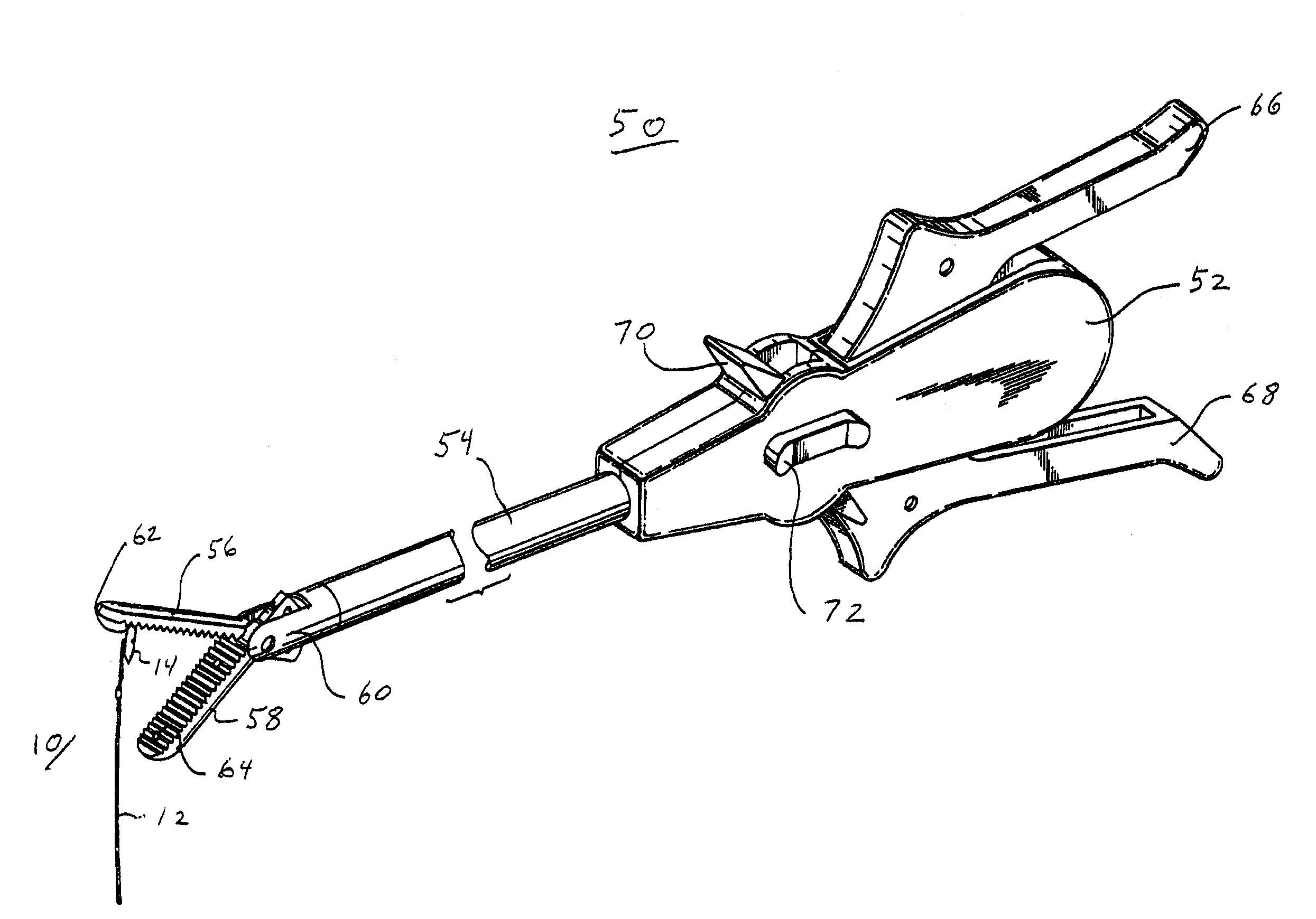
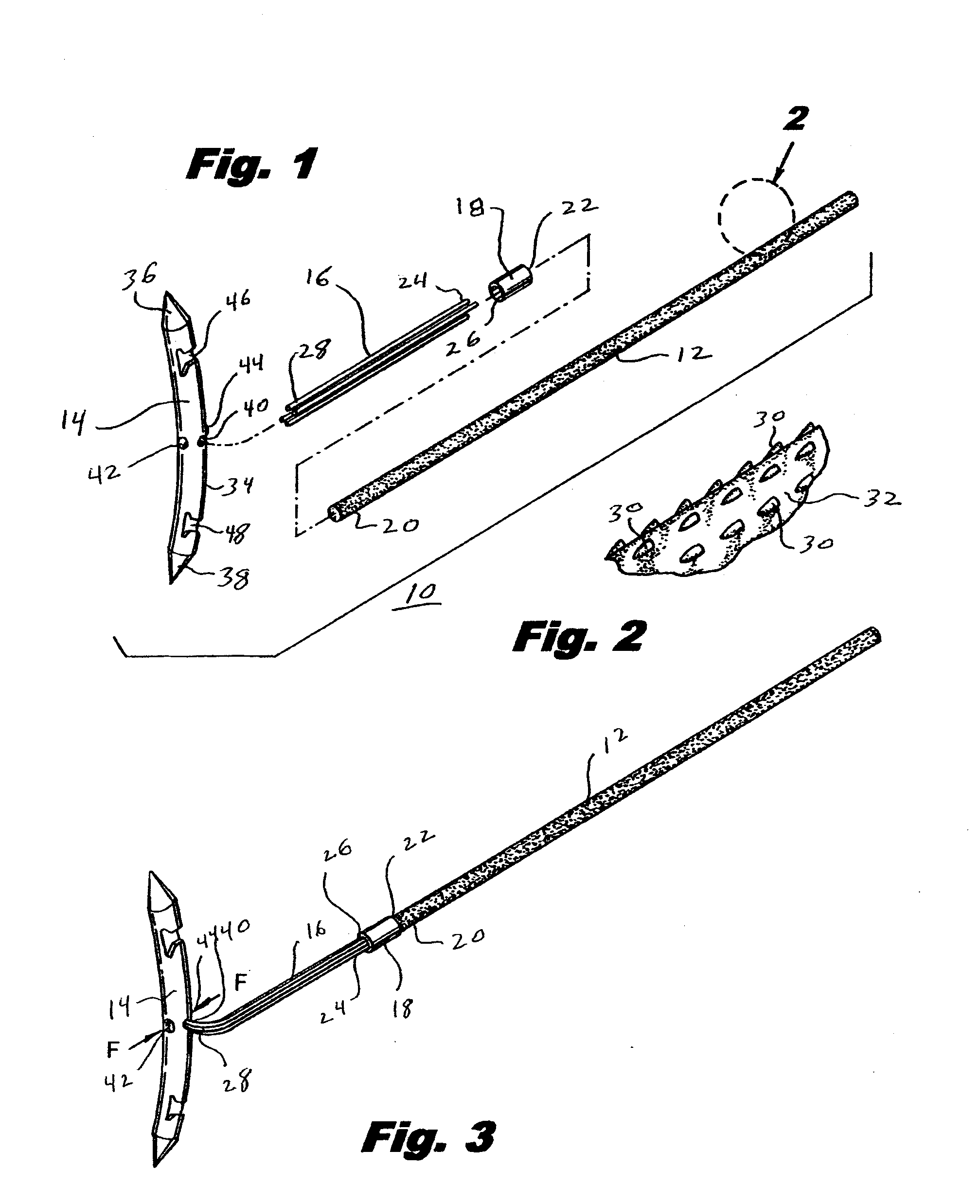
[0041]Referring to FIG. 1, there is disclosed a suture deployment system 10 for use in carrying, and manipulating, a relatively stiff target suture 12 of suture deployment system 10 into the body of a patient. Suture deployment system 10 generally includes target suture 12 and a surgical needle 14 for piercing tissue so as to position target suture 12 therethrough. A relatively flexible suture 16 is positioned between surgical needle 14 and target suture 12 and allows surgical needle 14 to be manipulated within a body cavity and through ...
PUM
Abstract
A suture deployment system is disclosed including a surgical needle having a flexible suture fixedly attached thereto and a target suture releasably secured to the flexible suture. A collar is positioned between the flexible suture and the target suture and is fixedly secured to the flexible suture. The target suture is releasably secured to the collar is such that the target suture may detach from the collar once a surgical procedure has been completed. The surgical needle is a double pointed surgical needle specifically configured to be manipulated by a surgical suturing apparatus.
Description
CROSS-REFERENCE TO RELATED APPLICATION[0001]The present application claims the benefit of and priority to U.S. Provisional Application Ser. No. 61 / 123,900, filed on Apr. 11, 2008, the entire content of which is incorporated herein by reference.[0002]The present application also claims the benefit of and priority to International Application Serial No. PCT / US07 / 21482, filed on Oct. 4, 2007, International Application Serial No. PCT / US07 / 21412, filed on Oct. 5, 2007, International Application Serial No. PCT / US07 / 21447, filed on Oct. 5, 2007, International Application Serial No. PCT / US07 / 21449, filed on Oct. 5, 2007, International Application Serial No. PCT / US07 / 21457, filed on Oct. 5, 2007, International Application Serial No. PCT / US07 / 21466, filed on Oct. 5, 2007, International Application Serial No. PCT / US07 / 21495, filed on Oct. 5, 2007, International Application Serial No. PCT / US07 / 21496, filed on Oct. 5, 2007, International Application Serial No. PCT / US07 / 21506, filed on Oct. 5, 20...
Claims
Application Information
Patent Timeline
Application Date:The date an application was filed.
Publication Date:The date a patent or application was officially published.
First Publication Date:The earliest publication date of a patent with the same application number.
Issue Date:Publication date of the patent grant document.
PCT Entry Date:The Entry date of PCT National Phase.
Estimated Expiry Date:The statutory expiry date of a patent right according to the Patent Law, and it is the longest term of protection that the patent right can achieve without the termination of the patent right due to other reasons(Term extension factor has been taken into account ).
Invalid Date:Actual expiry date is based on effective date or publication date of legal transaction data of invalid patent.
Patent Type & AuthorityApplications(United States)

