Surgical stapling instrument incorporating a multistroke firing position indicator and retraction mechanism

a multi-stroke, retraction mechanism technology, applied in the direction of surgical staples, surgical forceps, applications, etc., can solve the problems that the release of the firing trigger may not be indicative of a returned firing mechanism, and achieve the effect of enhancing the limited amount of information and control provided by the firing trigger

Active Publication Date: 2008-04-29
CILAG GMBH INT
View PDF53 Cites 2128 Cited by
  • Summary
  • Abstract
  • Description
  • Claims
  • Application Information

AI Technical Summary

Problems solved by technology

Moreover, release of the firing trigger may also not be indicative of a returned firing mechanism if binding has occurred.

Method used


Image

  • Surgical stapling instrument incorporating a multistroke firing position indicator and retraction mechanism
  • Surgical stapling instrument incorporating a multistroke firing position indicator and retraction mechanism
  • Surgical stapling instrument incorporating a multistroke firing position indicator and retraction mechanism

Examples


Embodiment Construction

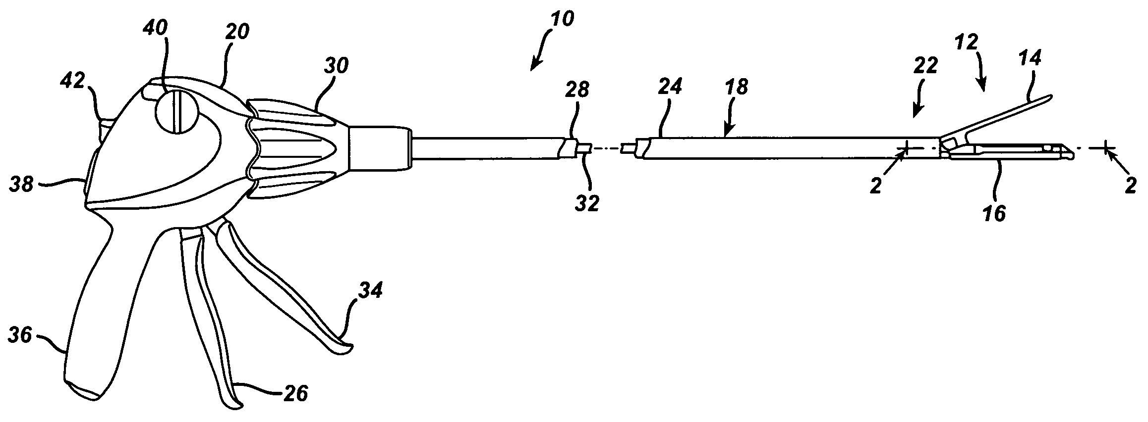
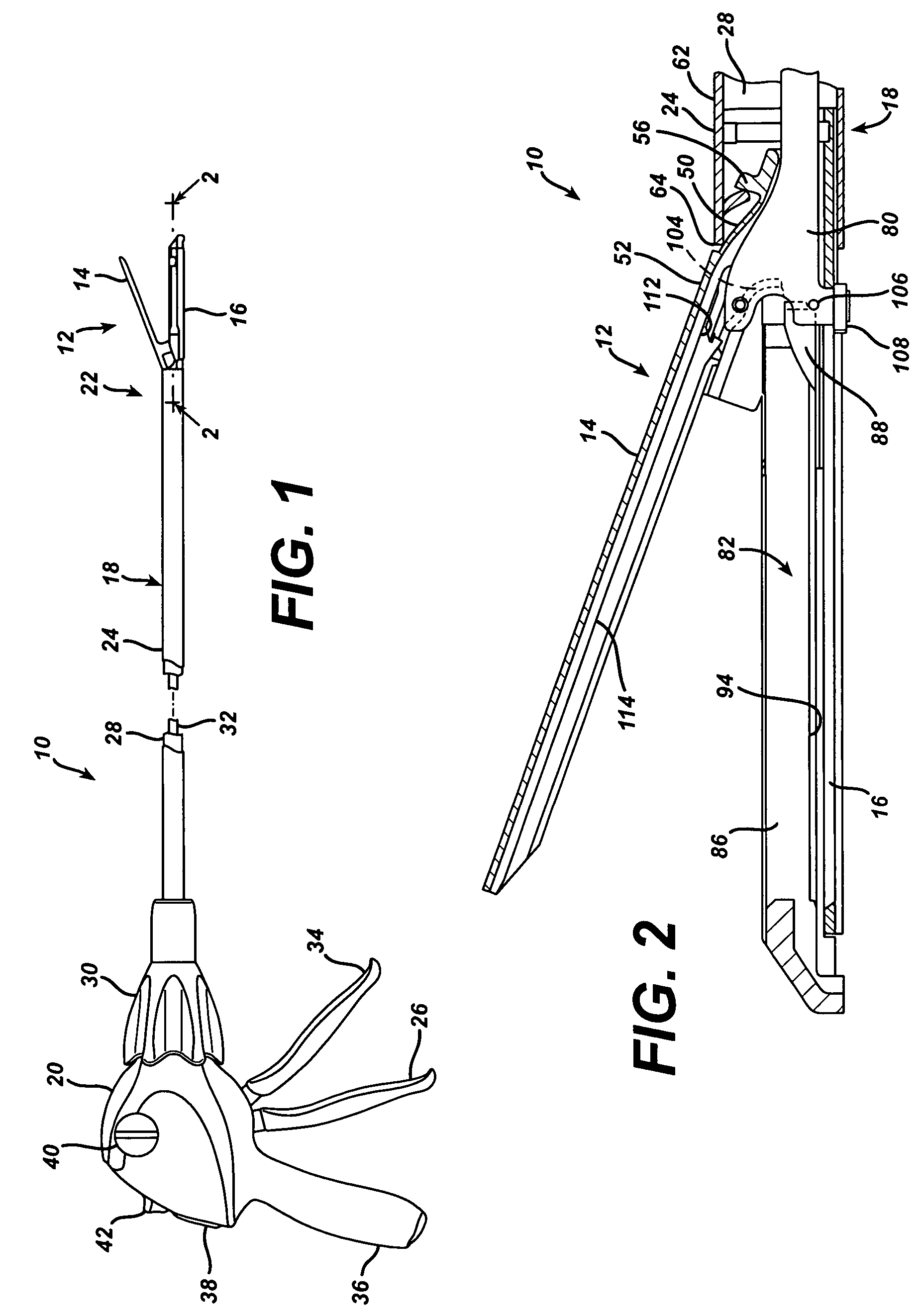
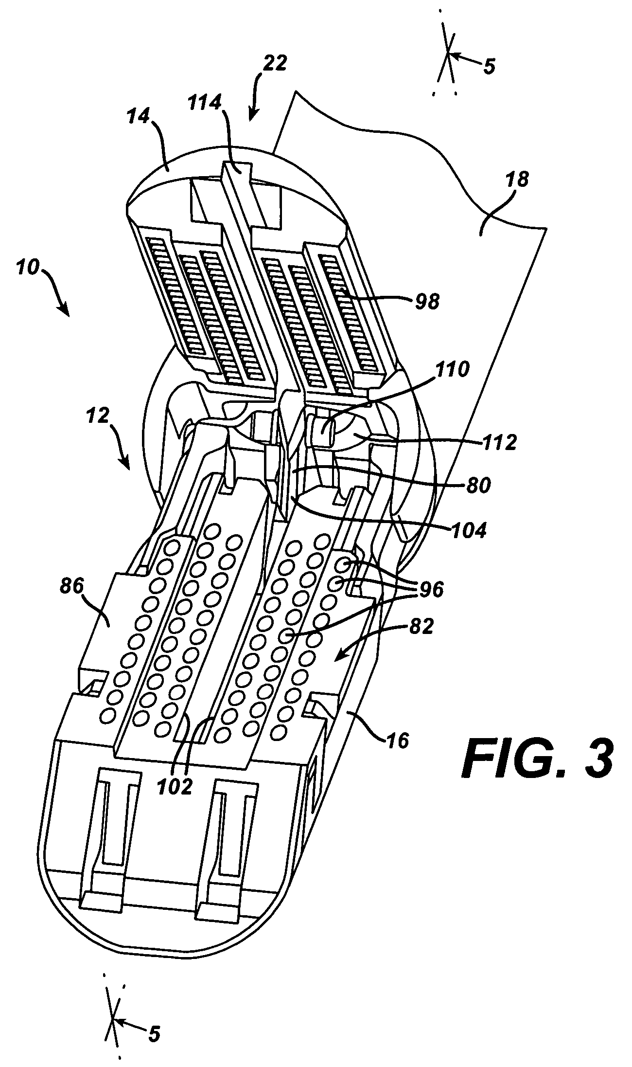
[0041]Turning to the Drawings, wherein like numerals denote like components throughout the several views, FIGS. 1 and 2 depict a surgical stapling and severing instrument 10 that is capable of practicing the unique benefits of the present invention. The surgical stapling and severing instrument 10 incorporates an end effector 12 having an anvil 14 pivotally attached to an elongate channel 16, forming opposing jaws for clamping tissue to be severed and stapled. The end effector 12 is coupled by a shaft 18 to a handle 20. An implement portion 22, formed by the end effector 12 and shaft 18, is advantageously sized for insertion through a trocar or small laparoscopic opening to perform an endoscopic surgical procedure while being controlled by a surgeon grasping the handle 20. The handle 20 advantageously includes features that allow separate closure motion of the end effector 12 from firing, as well as enabling multiple firing strokes to effect firing (i.e., severing and stapling) of t...


PUM

PropertyMeasurementUnit
sizesaaaaaaaaaa
lengthaaaaaaaaaa
forceaaaaaaaaaa

Abstract

A surgical stapling and severing instrument particularly suited to endoscopic procedures incorporates a handle that produces separate closing and firing motions to actuate an end effector. In particular, the handle produces multiple firing strokes in order to reduce the required amount of force required to fire (i.e., staple and sever) the end effector. A linked transmission reduces the required handle longitudinal length, yet achieves a rigid, strong configuration when straightened for firing. A traction biased firing mechanism avoids binding in driving this straightened linked rack in cooperation with an anti-backup mechanism, with a lockout mechanism that prevents releasing the closure trigger during firing. Furthermore, an external indicator gives feedback to the surgeon as to how far firing has progressed, as well as providing a manual retraction capability.

Description

CROSS REFERENCE TO RELATED APPLICATIONS[0001]The present application is related to four co-pending and commonly-owned applications filed on even date herewith, the disclosure of each is hereby incorporated by reference in their entirety, these four applications being respectively entitled:[0002]“SURGICAL STAPLING INSTRUMENT WITH MULTISTROKE FIRING INCORPORATING AN ANTI-BACKUP MECHANISM”, Ser. No. 10 / 673,852 to Frederick E. Shelton, Mike Setser, and issued as U.S. Pat. No. 6,959,852 on Nov. 1, 2005;[0003]“SURGICAL STAPLING INSTRUMENT HAVING MULTISTROKE FIRING WITH OPENING LOCKOUT”, Ser. No. 10 / 674,236, to Frederick E. Shelton, Jeffrey S. Swayze, Douglas B. Hoffman;[0004]“SURGICAL STAPLING INSTRUMENT INCORPORATING A FIRING MECHANISM HAVING A LINKED RACK TRANSMISSION”, Ser. No. 10 / 673,930, to Jeffrey S. Swayze, Frederick E. Shelton IV, and and issued as U.S. Pat. No. 6,905,057 on Jun. 14, 2005;[0005]“SURGICAL STAPLING INSTRUMENT HAVING MULTISTROKE FIRING INCORPORATING A TRACTION-BIASED...

Claims


Application Information

Patent Timeline
Patent Type & Authority Patents(United States)
IPC IPC(8): A61B17/072A61B17/068A61B1/00A61B17/115A61B17/28A61B19/00
CPCA61B17/07207A61B17/29A61B2017/2923A61B2017/2925A61B2017/2946A61B2019/4857A61B2090/0811
Inventor SWAYZE, JEFFREY S.SHELTON, IV, FREDERICK E.
Owner CILAG GMBH INT
Why Eureka
Try Eureka