Smoke curtain

a curtain and smoke technology, applied in the field of smoke curtain, can solve the problems of many, if not the majority, fire related deaths, and people escaping from fire on the wrong side of the curtain, and achieve the effect of improving the smoke curtain

Inactive Publication Date: 2009-10-29
COOPERS FIRE LTD
View PDF5 Cites 10 Cited by
  • Summary
  • Abstract
  • Description
  • Claims
  • Application Information

AI Technical Summary

Problems solved by technology

However, it is recognised that many, if not the majority of, fire related deaths occur as result of asphyxia from smoke from the fire.
Deployment of smoke curtains at an early stage of a fire is important, but can result in people escaping from the fire being on the wrong side of the curtain.

Method used


Image

  • Smoke curtain
  • Smoke curtain
  • Smoke curtain

Examples


Embodiment Construction

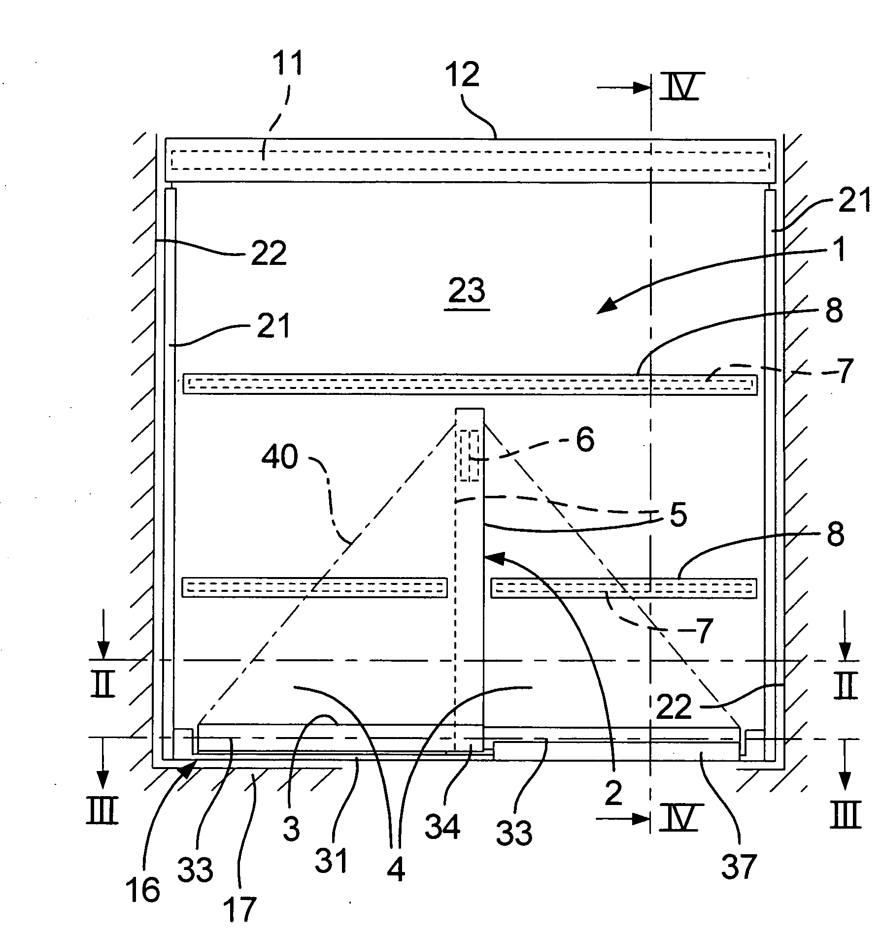
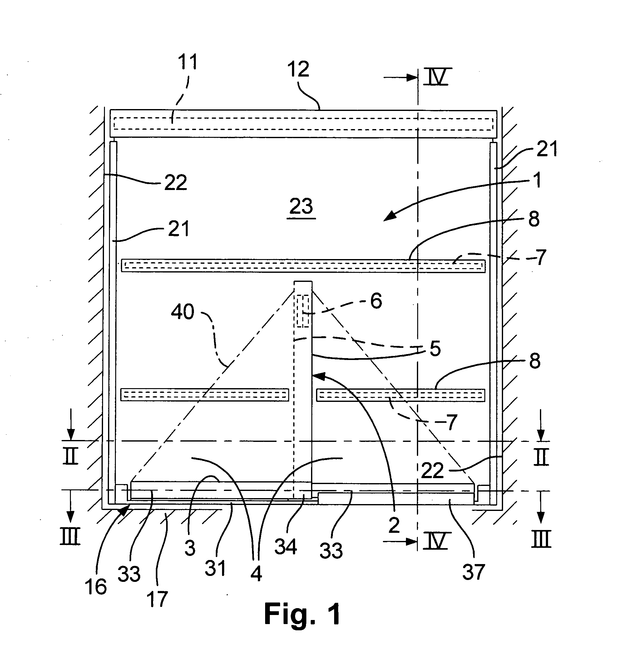
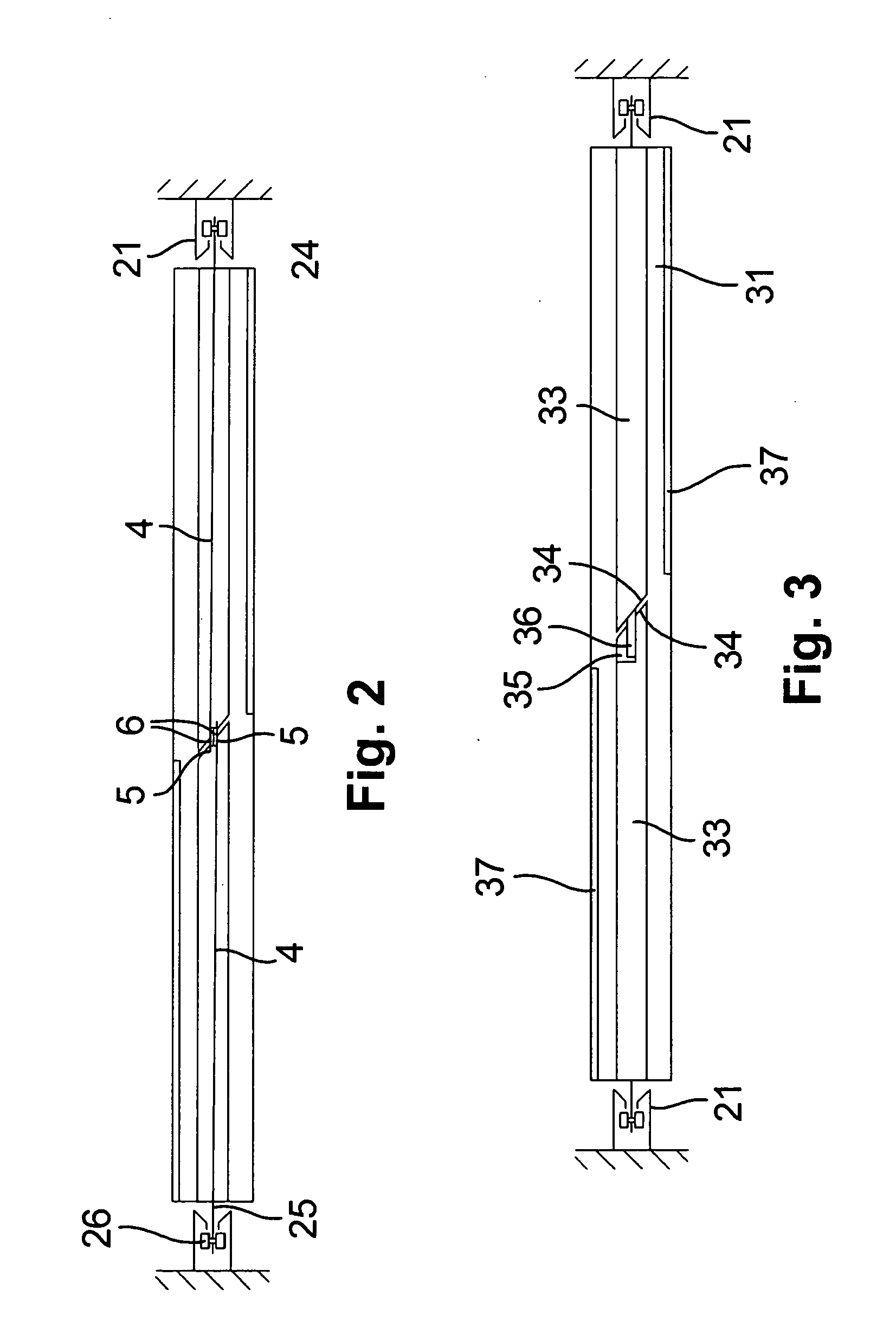
[0043]Referring first FIGS. 1 to 4 of the drawings, the curtain I shown is of heat resistant material, typically EFP2 / 1000S material from Coopers Fire Limited, Havant, England. When deployed, it has a vent 2 typically extending up 2½ metres from a bottom edge 3, the drop of the curtain being typically 4 metres. At the vent, flaps 4 of the curtain on either side of the vent have marginal overlaps 5. To these are stitched elevated temperature resistant hook and loop fastening tapes 6. These normally keep the vent closed.

[0044]Both above and below the extent of the vent, the curtain has horizontal stiffening battens 7 in pockets 8.

[0045]When not deployed, the curtain is wound on a roller 11 in a head box 12, mounted in a ceiling 14. The head box is provided with a seal 15 positioned to bear against the curtain when the latter is deployed, to close any smoke flow route in the head box and past the roller. The curtain is provided with a bottom bar 16 drawn up to close the head box when t...


PUM


Abstract

A heat resistant curtain has a vent typically extending up from a bottom edge. At the vent, flaps of the curtain on either side of the vent have marginal overlaps. To these are stitched elevated temperature resistant hook and loop fastening tapes. These normally keep the vent closed. The curtain is provided with a bottom bar drawn up to close the head box when the curtain is not deployed. When the curtain is deployed, the bottom bar rests on the floor.

Description

CROSS REFERENCE TO RELATED APPLICATION[0001]This application takes priority from and claims the benefit of United Kingdom Patent Application Serial No. 0806117.8 filed on Apr. 4, 2008.BACKGROUND OF THE INVENTION[0002]1. Field of the Invention The present invention relates to a smoke curtain.[0003]2. Description of the Related Art[0004]In a building fire, it is clearly desirable for the fire to be contained. However, it is recognised that many, if not the majority of, fire related deaths occur as result of asphyxia from smoke from the fire. For this reason, fire regulations now have a greater emphasis on smoke containment than previously.[0005]Deployment of smoke curtains at an early stage of a fire is important, but can result in people escaping from the fire being on the wrong side of the curtain. The present invention addresses this.SUMMARY OF THE INVENTION[0006]The object of the present invention is to provide an improved smoke curtain.[0007]According to a first aspect of the inv...

Claims


Application Information

Patent Timeline
Patent Type & Authority Applications(United States)
IPC IPC(8): A47H23/01A44B21/00A44B18/00E06B9/56A44B99/00
CPCA62C2/10E06B9/13E06B2009/17053Y10T24/44Y10T24/27
Inventor COOPER, ANDREW PAULREED, JAMES MARTIN
Owner COOPERS FIRE LTD
Why Eureka
Try Eureka