
Mechanical attachment system and associated failure mechanism

a technology of mechanical attachment and failure mechanism, which is applied in the direction of screws, fastening means, rod connections, etc., can solve the problems of complex cutting and re-welding operation, high abrasion environment, and significant wear, and achieves limited use of devices, time-consuming and relatively expensive,

Inactive Publication Date: 2009-11-19
SANDVIK SHARK
View PDF31 Cites 48 Cited by
  • Summary
  • Abstract
  • Description
  • Claims
  • Application Information

AI Technical Summary

Benefits of technology

[0015]The compressing member may be substantially cylindrical in shape. In a preferred embodiment, the compressing member has a bevelled outer edge, located within the p

Problems solved by technology

Ground engaging tools (GET), for earth-moving equipment, such as those used in mining operations, operate in a highly abrasive environment and are subject to significant wear.
It will be appreciated that the cutting and re-welding operation is complex, time-consuming and relatively expensive.
In general, such devices have proved to be of limited use.
The insertion of a bolt or similar within a bucket lip can lead to undesi

Method used


Image

  • Mechanical attachment system and associated failure mechanism
  • Mechanical attachment system and associated failure mechanism
  • Mechanical attachment system and associated failure mechanism

Examples


Embodiment Construction

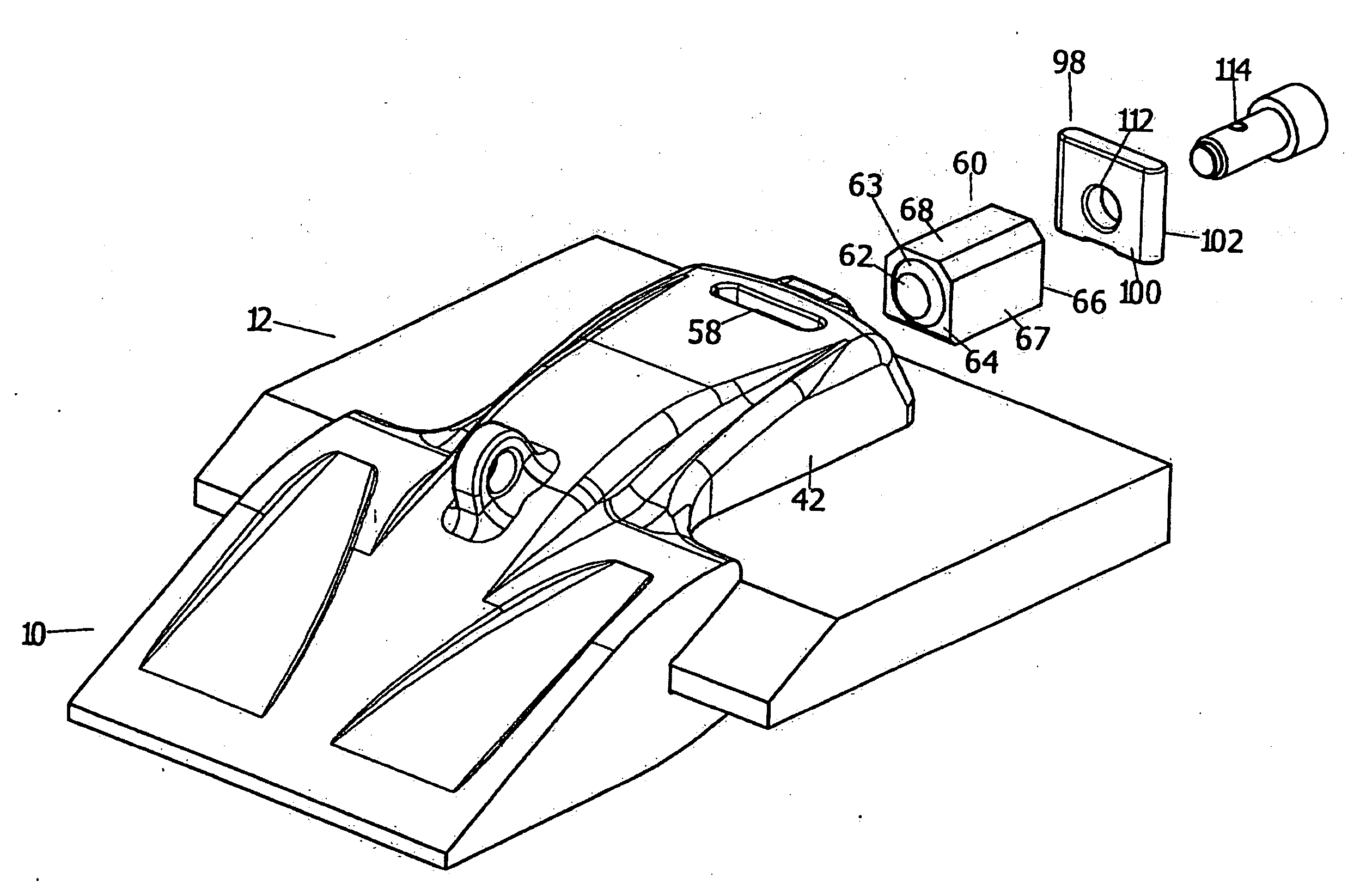
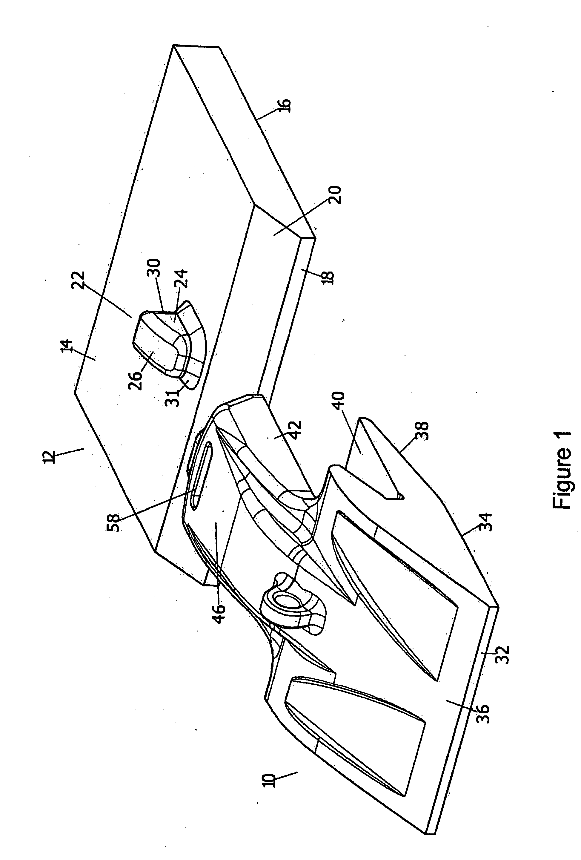
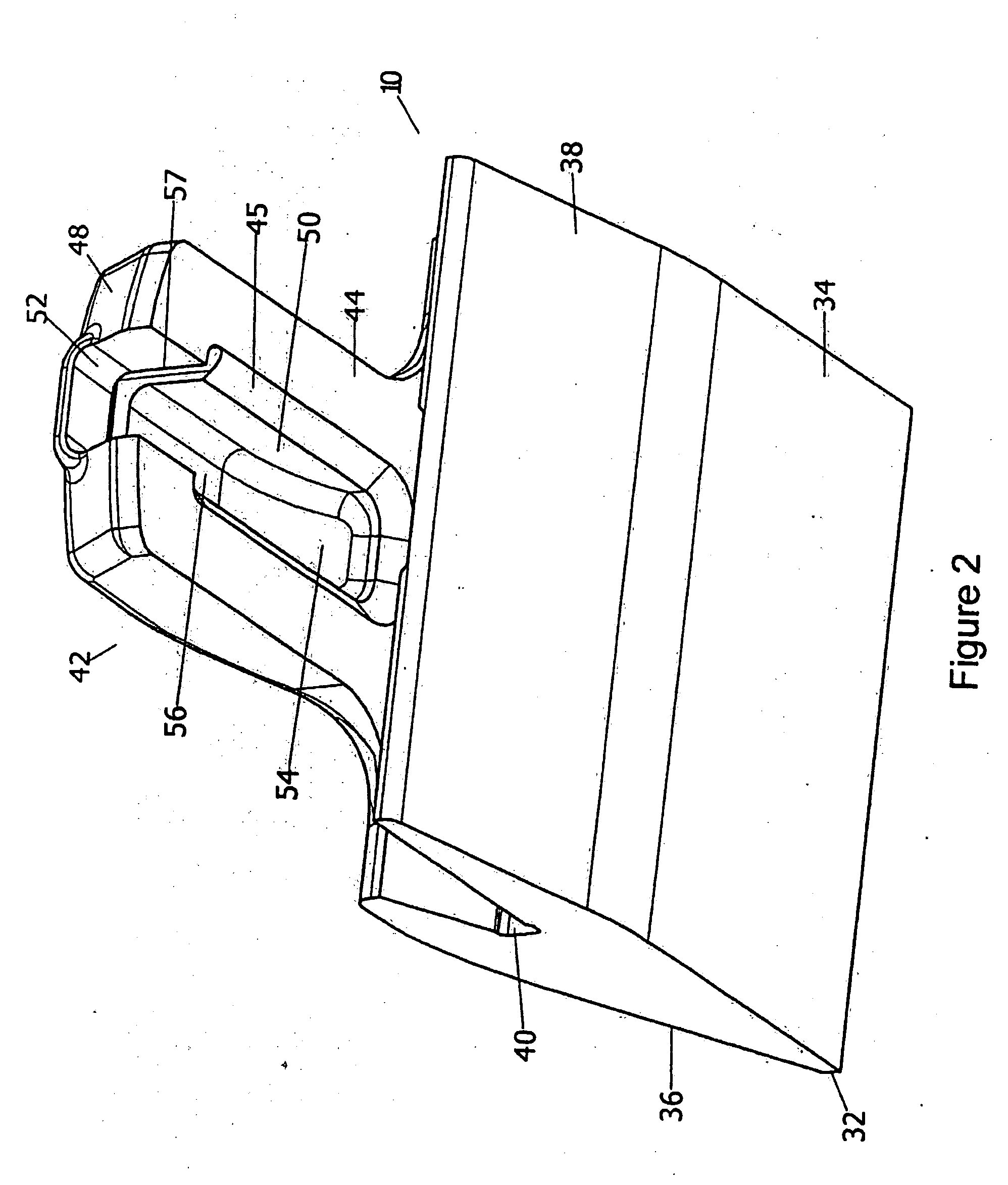
[0026]Referring to the Figures, there is shown a ground engaging tool 10 arranged to be attached to a portion of a lip plate 12. The lip plate 12 is substantially rectangular in cross section, and extends around the rim of a bucket (not shown) of a mechanical digging device. The lip plate 12 includes an upper face 14, a lower face 16 and an end face 18. A tapered surface 20 extends from the end face 18 of the lip plate 12 to the upper face 14.

[0027]The lip plate 12 includes a lug 22 affixed by suitable means to the upper face 14. In the embodiment shown in the drawings the lug 22 is affixed by a weld 31. The lug 22 is oriented towards the end face 18 of the lip plate 12, and includes a top surface 26 which curves upwardly in a convex fashion from a first end of the lug 22 adjacent the tapered surface 20 to a second end of the lug 22 remote from the tapered surface 20.

[0028]The lug 22 further includes a substantially flat rear face 30 at the second end of the lug 22, the rear face 30...


PUM


Abstract

An attachment system for connecting a first member such as a lip plate of a mechanical digging device to a second member such as a ground engaging tool. The first member has a lug attached thereto, and the second member has a recess which is located about the lug A stabilizing member is located within a slot in the recess. A clamping member is between the lug and the stabilizing member, and includes a resilient portion such as a compression spring. A compressive force supplied to the resilient portion restricts the movement of the second member relative to the lug.

Description

CROSS-REFERENCE TO RELATED APPLICATION[0001]This application is a Continuation-in-Part of application Ser. No. 10 / 509,016 filed Apr. 7, 2005 which is a National Stage Application of PCT / AU03 / 00362 filed Mar. 26, 2003, and claims the priority of Australian Application No. PS1348, filed Mar. 26, 2002, and Australia Application No. 2002950166, filed Jul. 12, 2002, both priorities being claimed herein. The priority of Australian Provisional Application No. 2008906335, filed Dec. 8, 2008 is also claimed herein. The entire content of the foregoing earlier applications is incorporated herein by reference.FIELD OF THE INVENTION[0002]The present invention relates to mechanical connections of wear parts to underlying structures. It has been created in connection with the connection of ground engaging tools to buckets of earth-moving equipment.BACKGROUND OF THE INVENTION[0003]Many mining and earthmoving operations require the use of mechanical digging devices, such as front-end loaders. Such m...

Claims


Application Information

Patent Timeline
IPC IPC(8): E02F9/28F16B1/00F16B35/00
CPCE02F9/2841Y10T403/7069Y10T403/7064
Inventor NAHER, PATRICK GERARDHUGHES, BENJAMIN
Owner SANDVIK SHARK
Learn More