
Force-responsive orthodontic brackets and systems and methods which use the same

a technology of orthodontic brackets and force-responsive brackets, which is applied in the field of orthodontic brackets, can solve the problems of high subjective effort in the adjustment of the archwire, and achieve the effect of improving the stability and stability of the archwir

Inactive Publication Date: 2009-11-19
SEARS ROBERT S +1
View PDF4 Cites 91 Cited by
  • Summary
  • Abstract
  • Description
  • Claims
  • Application Information

AI Technical Summary

Benefits of technology

[0005]Broadly, the present invention is embodied in a force-responsive orthodontic bracket. More specifically, the orthodontic bracket of the present invention allows for the objective determination of the magnitude and / or direction of force applied to the tooth to which the bracket is attached. The present invention is therefore preferably embodied in orthodontic brackets having an elastomeric member which allows at least one portion of the bracket to be resiliently movable relative to at least one other portion of the bracket in response to an applied force. At least one force-responsive sensor may be operatively associated with the orthodontic bracket for generating a detectable signal in response to movement of the at least one and other portions of the bracket.

Problems solved by technology

Adjustment of the archwire is, however, a highly subjective endeavor.

Method used


Image

  • Force-responsive orthodontic brackets and systems and methods which use the same
  • Force-responsive orthodontic brackets and systems and methods which use the same
  • Force-responsive orthodontic brackets and systems and methods which use the same

Examples


Embodiment Construction

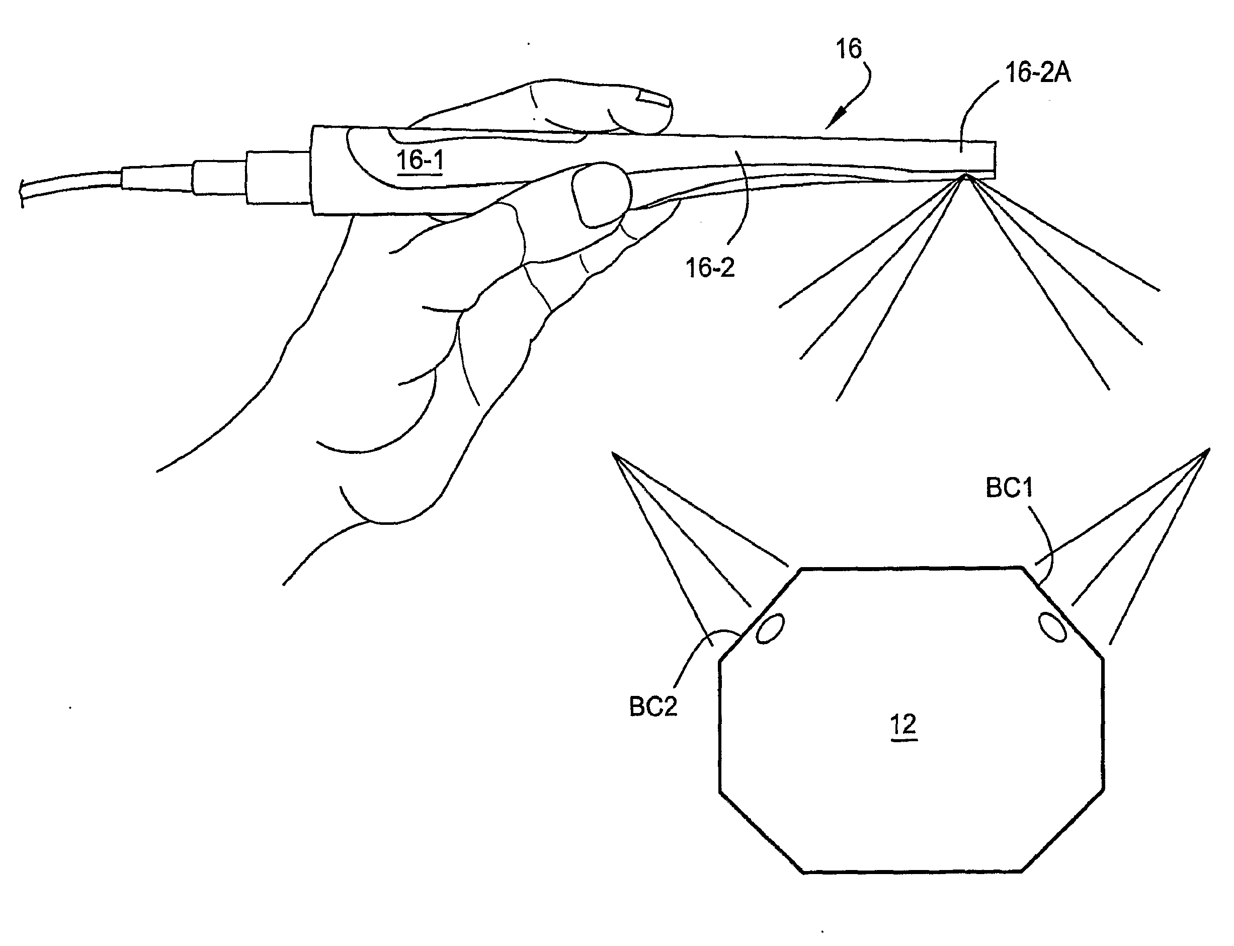
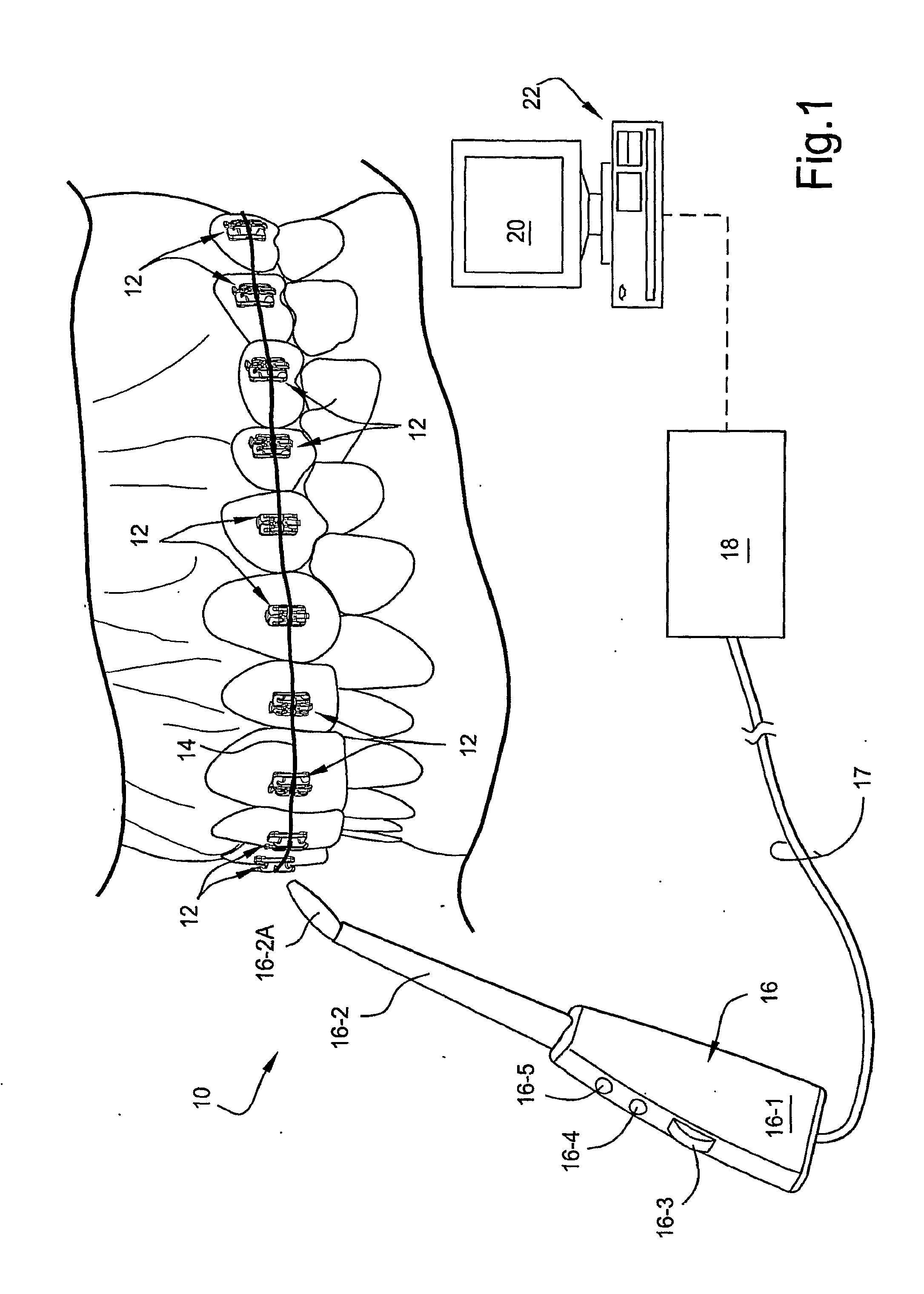
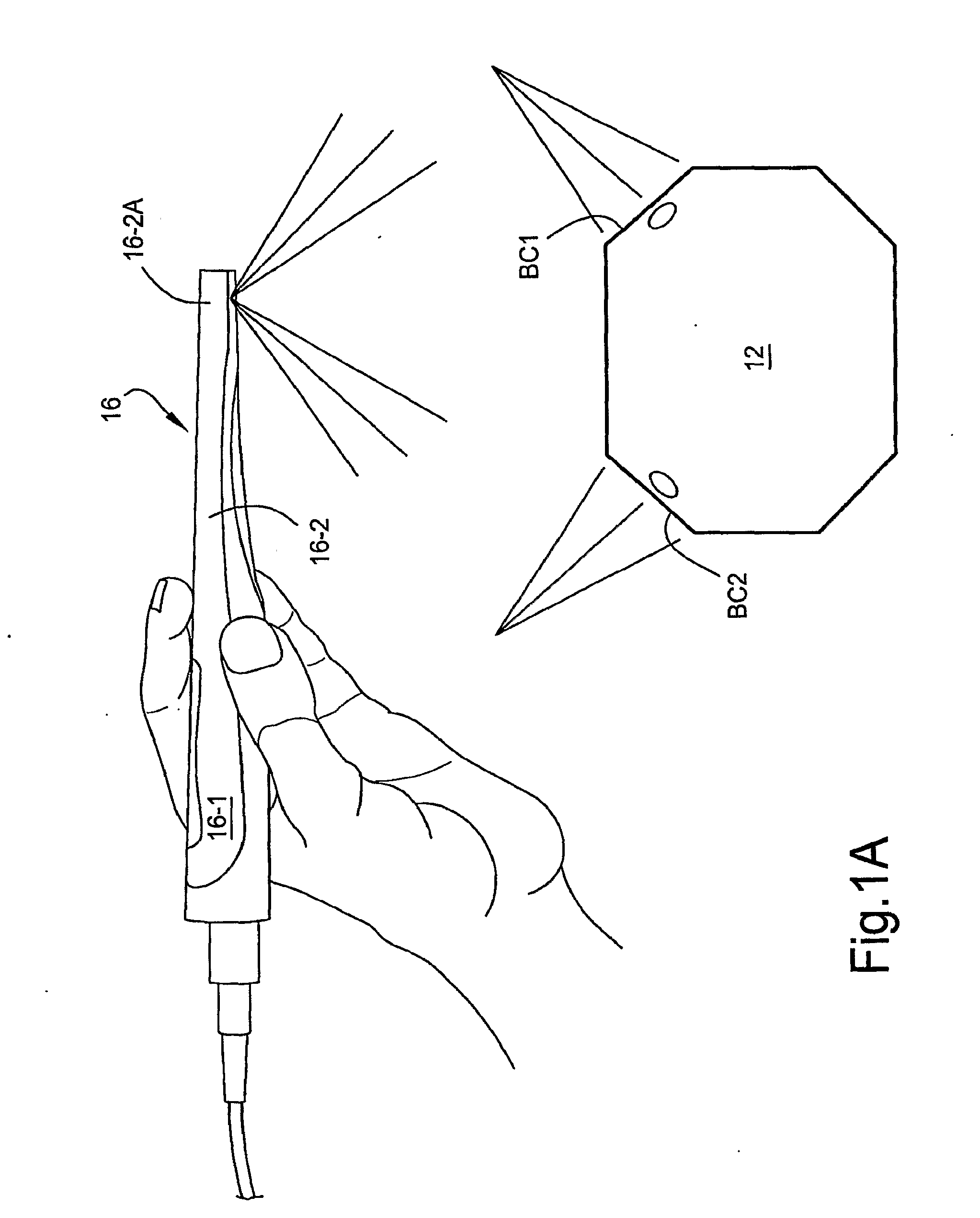
[0019]Accompanying FIG. 1 depicts schematically a system 10 according to the present invention which is especially adapted to detect and present the magnitude and / or direction of force associate with individual ones of the orthodontic brackets 12 which are bonded to the front surfaces of respective teeth in a patient's mouth. As will be explained in greater detail below, the individual brackets 12 are provided with fiducial markings that are indicative of the magnitude and / or direction of force applied to the brackets 12 by means of the archwire 14.

[0020]Generally, according to the present invention, the fiducial markings may be detected optically by means of a hand-held detector 16 which is connected operatively to a central processor 18 by signal line 17. The central processor 18 thus receives an output signal generated by means of the detector 16 via the signal line 17 and is programmed with the necessary algorithms which translate the output signal representative of the opticall...


PUM


Abstract

Force magnitudes and / or directions may be determined objectively using orthodontic brackets having an elastomeric member which allows one portion of the bracket to be resiliently moveable relative to at least on other portion of the bracket. In a preferred embodiment, the brackets include a lower base member, an upper bracket member, and an elastomeric layer interposed between the lower base and upper bracket members. The orthodontic bracket is advantageously employed as part of a system whereby the orthodontic bracket includes an elastomeric member which allows at least one portion of the bracket to be resiliently movable relative to at least one other portion of the bracket in response to an applied force, and at least one force-responsive sensor operatively associated with the orthodontic bracket for generating a detectable signal in response to movement of the at least one and other portions of the bracket. A detector is provided so as to allow for the wireless detection of the force-responsive signal generated by the force-responsive sensor and issue an output signal in response thereto. A processor receives the output signal from the detector to provide an indication of magnitude and / or direction of the force applied to the orthodontic bracket.

Description

CROSS-REFERENCE TO PRIORITY APPLICATION[0001]This application is based on and claims priority benefits under 35 USC § 119 from U.S. Provisional Application Ser. No. 60 / 796,523 filed on May 2, 2006, the entire content of which is expressly incorporated hereinto by reference.FIELD OF THE INVENTION[0002]The present invention relates generally to the field of orthodontics. In especially preferred embodiments, the present invention relates to orthodontic brackets which include a force-responsive component by which the magnitude and / or direction of an applied force may be determined optically.BACKGROUND AND SUMMARY OF THE INVENTION[0003]Orthodontic brackets typically are attached to individual teeth and connected to an archwire so as to apply appropriate force over time to move and straighten teeth. Specifically, teeth are moved and rotated by applying forces and / or torques to the brackets via the archwire. Periodic visits to the orthodontist are therefore required so that the assembly ma...

Claims


Application Information

Patent Timeline
Patent Type & Authority Applications(United States)
IPC IPC(8): A61C3/00
CPCA61C19/04A61C7/14
Inventor SEARS, ROBERT S.TRIMMER, WILLIAM S.
Owner SEARS ROBERT S
Learn More