
Linear motor

a linear motor and motor shaft technology, applied in the field of linear motors, can solve the problems of increasing the torque of the coil motor to an unacceptable level or beyond the allowable level, and achieve the effect of preventing electrical shorts and low manufacturing costs

Inactive Publication Date: 2009-12-10
SANYO DENKI CO LTD
View PDF5 Cites 9 Cited by
  • Summary
  • Abstract
  • Description
  • Claims
  • Application Information

AI Technical Summary

Benefits of technology

This configuration effectively reduces cogging torque to a practically acceptable level, improving the motor's performance and efficiency by maintaining a specific ratio of magnet lengths and using spacers to prevent electrical shorts.

Problems solved by technology

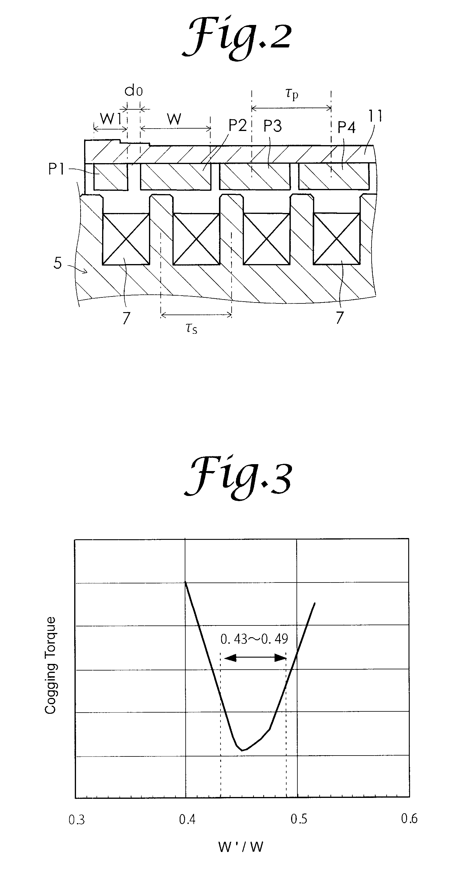
When the ratio W1 / W is 0.43 or less, or the ratio W1 / W is 0.49 or more, the cogging torque increases to an unacceptable level or beyond an allowable level.

Method used


Image

  • Linear motor
  • Linear motor
  • Linear motor

Examples


Embodiment Construction

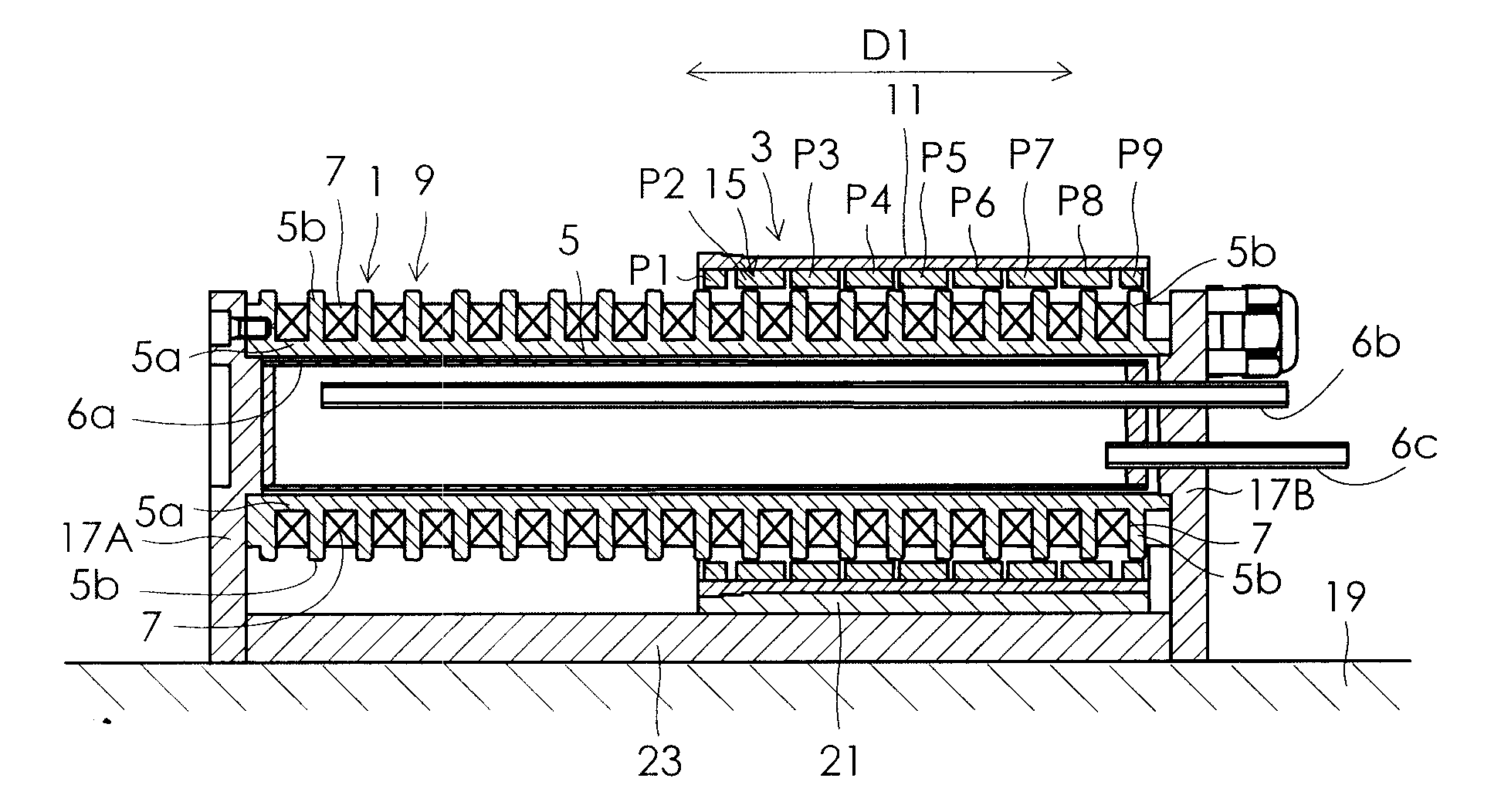
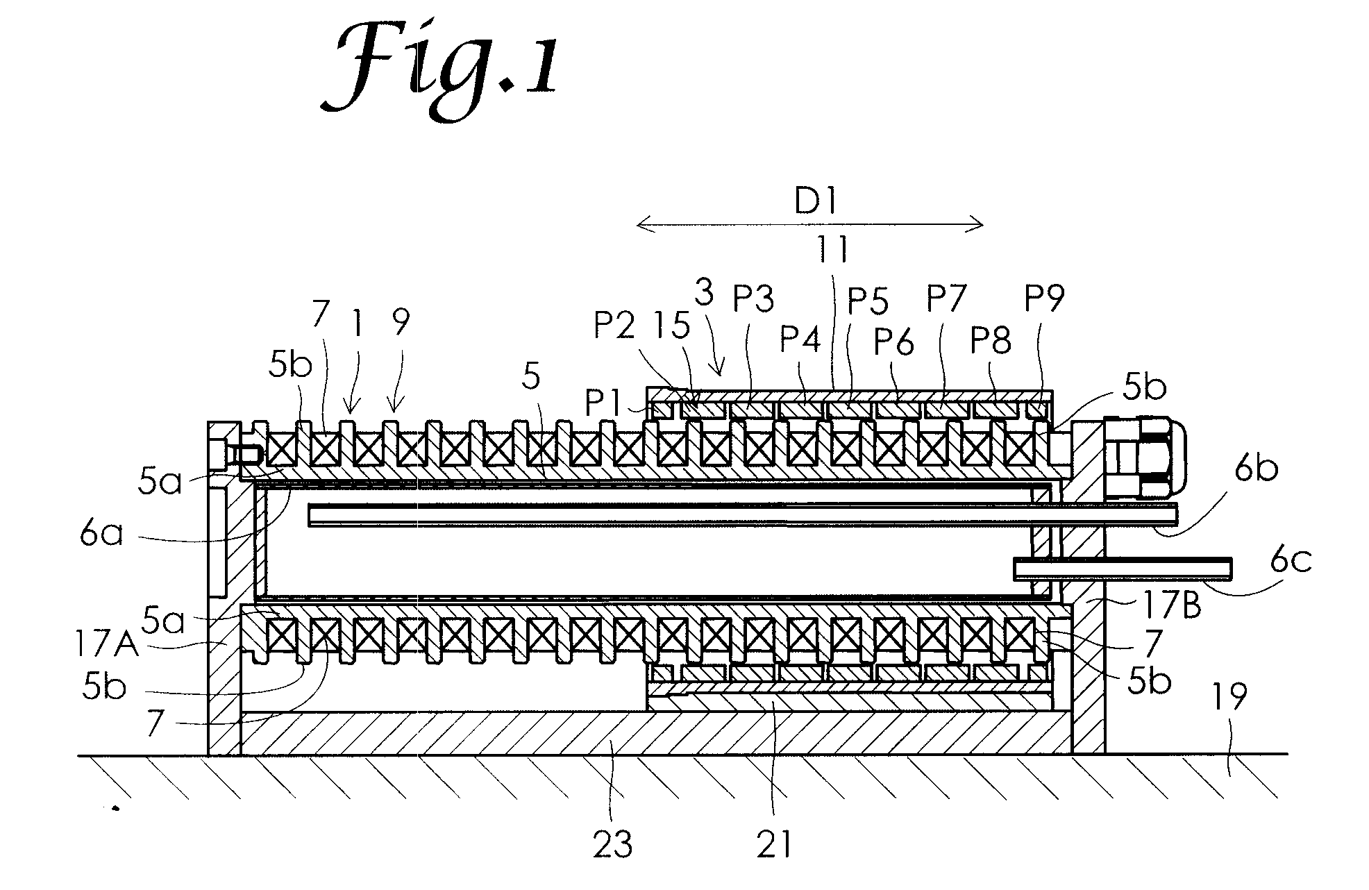
[0017]Preferred embodiments of the present invention will now be described with reference to the accompanying drawings. FIG. 1 is a cross-sectional view of a cylindrical linear motor according to one embodiment of the present invention. The linear motor of this embodiment includes a stator 1 and a movable element 3 as shown in FIG. 1. The stator 1 comprises an armature 9 that includes an iron core 5 and a plurality of armature windings 7. The iron core 5 has a cylindrical yoke 5a and a plurality of magnetic pole portions 5b extended from the yoke 5a. An annular slot is formed between two adjacent magnetic pole portions 5b. The plurality of armature windings 7 are respectively wound around the plurality of annular slots via insulators in a circumferential direction of the cylindrical yoke. In this embodiment, the plurality of armature windings 7 are disposed so that three phases are arranged in the order of U-phase, −U-phase, U-phase, V-phase, −V-phase, V-phase, W-phase, −W-phase, an...


PUM


Abstract

When a pitch between centers of two adjacent magnetic pole portions disposed on an armature is defined as τs, the length W of permanent magnets disposed in the middle is equal to the pitch τs (W=τs). The length of each of the two end permanent magnets respectively disposed at either end of a permanent magnet magnetic pole row is denoted by W1. A ratio w1 / W of the length W1 to the length W is defined as 0.43<W1 / W<0.49. With this definition, cogging torque of a linear motor may sufficiently be reduced.

Description

FIELD OF THE INVENTION[0001]The present invention relates to a linear motor. BACKGROUND OF THE INVENTION[0002]Japanese Patent Publication No. 11-308850 discloses a linear motor which includes a stator and a movable element so that the movable element may reciprocate with respect to the stator, and further includes an armature disposed on one of the stator and the movable element and a permanent magnet magnetic pole row disposed on the other of the stator and the movable element. The armature of the linear motor has an iron core having three or more magnetic pole portions arranged along a moving direction of the movable element, and armature windings of three phases respectively wound around the three or more magnetic pole portions of the iron core. The permanent magnet magnetic pole row has a frame of a nonmagnetic material and a plurality of permanent magnets disposed in through-holes formed in the frame. The plurality of permanent magnets are disposed at a given interval in a row ...

Claims


Application Information

Patent Timeline
Patent Type & Authority Applications(United States)
IPC IPC(8): H02K41/03
CPCH02K1/278H02K2213/03H02K41/031H02K29/03H02K41/02
Inventor TANG, YUQISUGITA, SATOSHI
Owner SANYO DENKI CO LTD
Learn More