
Variable speed belt

a variable speed belt and belt technology, applied in the direction of driving belts, belts/chains/gearrings, v-belts, etc., can solve the problem of high transversal stiffness

Inactive Publication Date: 2010-01-07
THE GATES CORP
View PDF8 Cites 30 Cited by
  • Summary
  • Abstract
  • Description
  • Claims
  • Application Information

AI Technical Summary

Problems solved by technology

To achieve maximum performance, efficiency, and durability, one of the main challenges the belt design faces is meeting contradictory requirements, high longitudinal flexibility but high transversal stiffness while maintaining proper side contact.

Method used


Image

  • Variable speed belt
  • Variable speed belt
  • Variable speed belt

Examples


Embodiment Construction

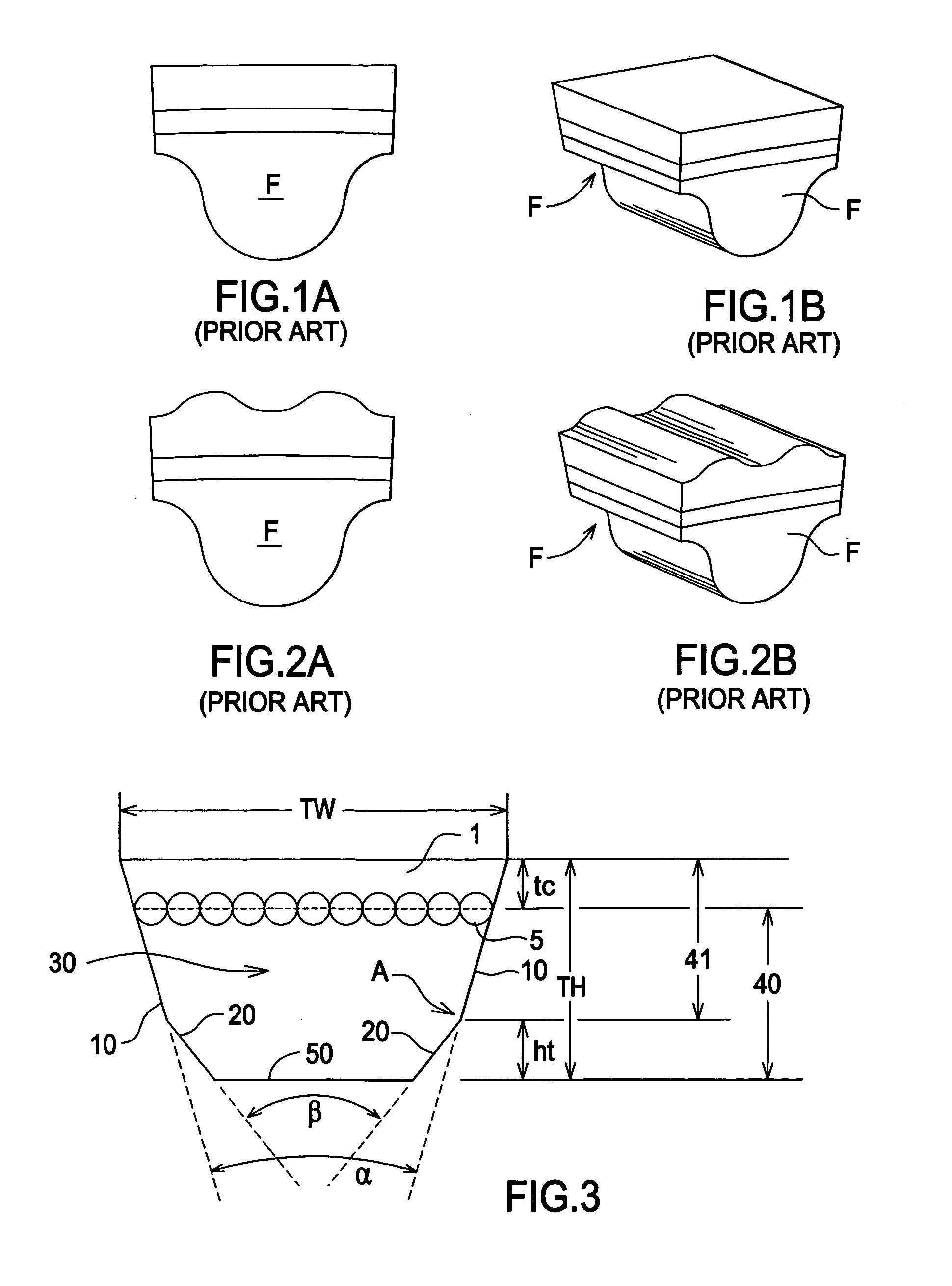
[0026]The invention comprises a cogged variable speed belt. To satisfy these special design requirements, a cogged V-belt design is adopted in variable speed drives. FIG. 1A is a side view of a prior art v-belt cog. FIG. 1B is a perspective view of the prior art v-belt cog in FIG. 1A.

[0027]To further increase transversal stiffness while still maintain high flexibility and suitable contact area, a double cog belt design, in which additional cogs are added on the top of belt, is conventionally used. FIG. 2A is a side view of a prior art v-belt cog. FIG. 2B is a perspective view of the prior art v-belt cog in FIG. 2A. However, the double cog design has drawbacks including a more complex manufacturing process and higher cost. In each prior art belt, cog opposing flanks (F) each contact a sheave during operation to transmit torque. Each flank (F) is substantially planar surface.

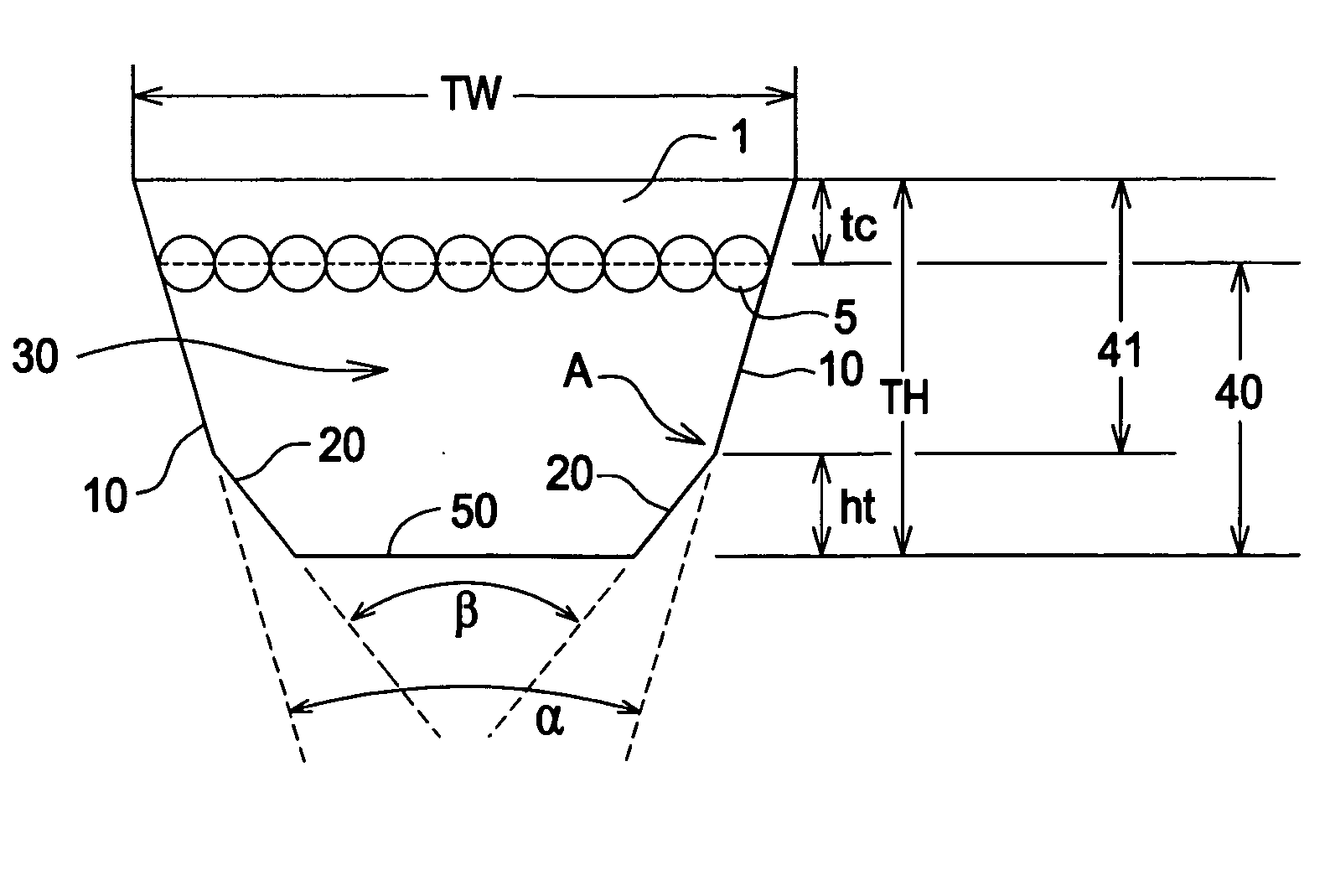
[0028]FIG. 3 is an elevation view of an inventive cog. The inventive belt comprises a body 1. Embedded within t...


PUM


Abstract

A variable speed belt comprising an elastomeric body, a tensile cord disposed within the elastomeric body and extending in an endless direction, a cog extending from the body, the cog comprising opposing flanks, each flank comprises a first planar surface describing an included angle (α), the first planar surface engageable with a sheave, each flank comprises a second planar surface disposed toward a cog tip describing an included angle (β); and included angle (α) is not equal to the included angle (β).

Description

FIELD OF THE INVENTION[0001]The invention relates to a variable speed belt, and more particularly, to a variable speed belt comprising a cog flank having a first planar surface disposed at a first angle for engaging a sheave and a cooperating second planar surface disposed at a second angle that is not engagable with a sheave surface.BACKGROUND OF THE INVENTION [0002]The belt plays an important role in the operation of variable speed power transmission systems. As a flexible element, the belt connects two pairs of sheaves through friction to transmit power from the driving shaft to the driven shaft. Each pair of sheaves includes a fixed sheave and a movable sheave. By controlling the axial movement of movable sheaves, the speed and torque ratio is changed. During operation, the belt sustains extreme longitudinal tension and transversal compression. To achieve maximum performance, efficiency, and durability, one of the main challenges the belt design faces is meeting contradictory re...

Claims


Application Information

Patent Timeline
Patent Type & Authority Applications(United States)
IPC IPC(8): F16G5/20
CPCF16G5/20
Inventor FAN, XINJIANBROWN, LESLEE WAYNEDUKE, RALPH M.SATO, YOSHITAKA
Owner THE GATES CORP
Features
  • Generate Ideas
  • Intellectual Property
  • Life Sciences
  • Materials
  • Tech Scout
  • Unparalleled Data Quality
  • Higher Quality Content
  • 60% Fewer Hallucinations
Learn More