Probe-array substrate, probe array, and method of producing the same

a technology applied in the field of probe array and substrate probe array, can solve the problems of substrate defective as probe array, cost or production speed sacrifice, etc., and achieve the effects of low cost, low cost, and efficient production of probe array

Inactive Publication Date: 2010-01-07
MURATA MFG CO LTD
View PDF9 Cites 47 Cited by
  • Summary
  • Abstract
  • Description
  • Claims
  • Application Information

AI Technical Summary

Benefits of technology

[0031]With the method of producing a probe array according to at least one of the embodiments of the present invention, many different types of probe solutions can be supplied from the supplying unit to the probe-array substrate at a single time. Therefore, the probe array can be produced efficiently at low cost. In filling the plurality of nozzles of the supplying unit with the probe solutions, it is necessary to fill the plurality of nozzles with different types of the probe solutions. This operation can be relatively time consuming and costly. However, because the probe solutions can be supplied to many probe-array substrates using a supplying unit and the pr...

Problems solved by technology

If an injection needle, micropipette, or ink jetting is used in spotting, it is necessary to change the solution for every one-point application, and this sacrifices cost or produ...

Method used


Image

  • Probe-array substrate, probe array, and method of producing the same
  • Probe-array substrate, probe array, and method of producing the same
  • Probe-array substrate, probe array, and method of producing the same

Examples


first embodiment

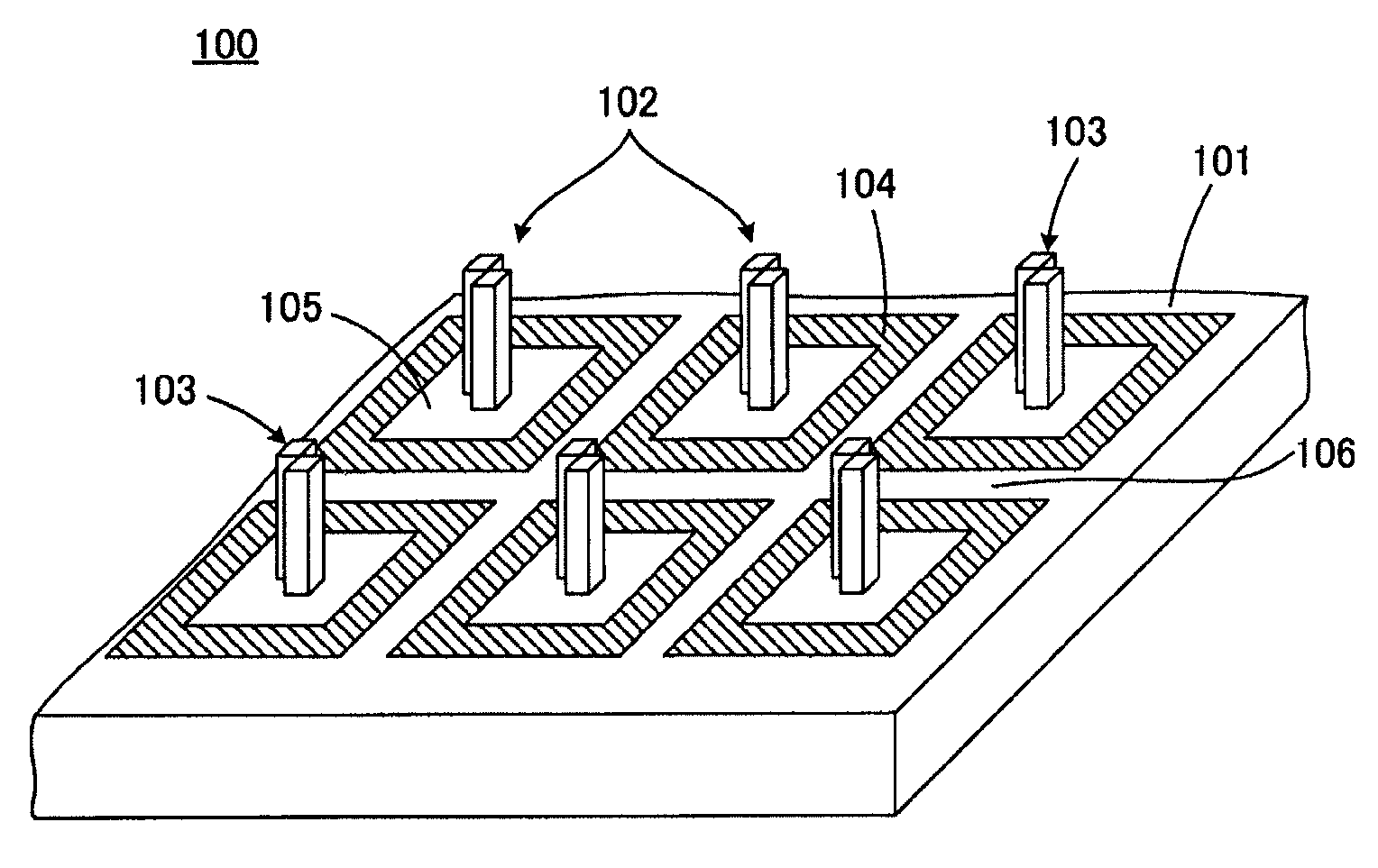
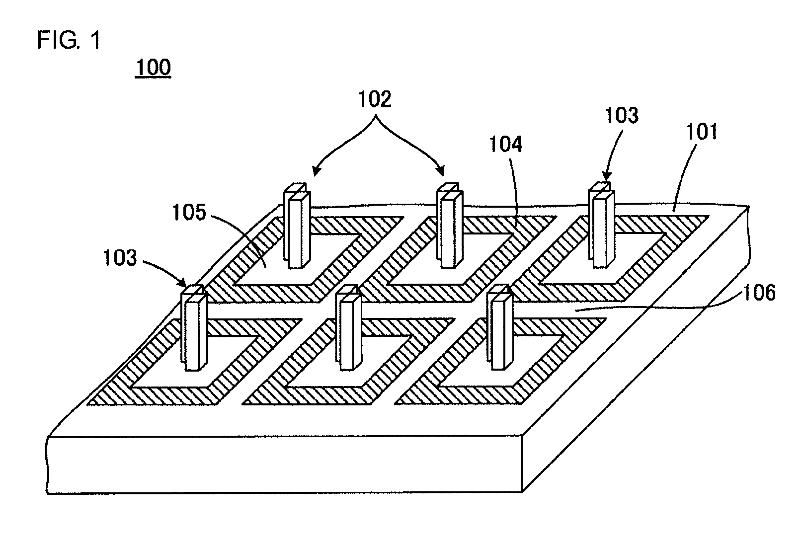
[0047]FIG. 1 illustrates in part of a probe-array substrate 100 according to the present invention in perspective view. FIG. 2 is a top view of a part of the probe-array substrate 100 shown in FIG. 1.

[0048]Referring to FIGS. 1 and 2, the probe-array substrate 100 includes a main surface 101 and is substantially planar as a whole. A plurality of probe holding units 102 are arranged in a matrix on the probe-array substrate 100.

[0049]Each of the probe holding units 102 includes a hydrophilic projection 103. The terms “hydrophilic” and “hydrophobic” are usually used as terms indicating the presence or absence of wettability (affinity) for water. In the following description, however, regardless of whether a probe solution is an aqueous solution, when wettability for a probe solution is high, the state is represented as “hydrophilic,” and when wettability therefor is low, the state is represented as “hydrophobic.”

[0050]Each of the probe holding units 102 is surrounded by a hydrophobic re...

second embodiment

[0116]FIG. 11 is an illustration for use in describing the present invention and corresponds to FIG. 2. In FIG. 11, similar reference numerals are used in the elements corresponding to those illustrated in FIG. 2, and the redundant description is omitted.

[0117]In a probe-array substrate 100a illustrated in FIG. 11, the hydrophilic region 105 forming a portion of the probe holding unit 102 and the inspection region 106 are coupled with a hydrophilic region 114 having a narrow width. The narrow hydrophilic region 114 is disposed therebetween and extends across the hydrophobic region 104. Even in this embodiment, if the width of the narrow hydrophilic region 114 is sufficiently small, a probe solution properly introduced in the probe holding unit 102 does not flow into the inspection region 106 through the narrow hydrophilic region 114. This is because when the probe solution is moving in the narrow hydrophilic region 114, if the width of the narrow hydrophilic region 114 is sufficient...

third embodiment

[0119]FIG. 12 is an illustration for use in describing the present invention and corresponds to FIG. 1. In FIG. 12, the same or similar reference numerals are used in the elements corresponding to those illustrated in FIG. 1, and the redundant description is omitted.

[0120]In a probe-array substrate 100b illustrated in FIG. 12, the probe holding unit 102 is provided by the projection 103 alone. Accordingly, the hydrophobic region 104 is the portion other than the portion where the projection 103 on the main surface 101 of the probe-array substrate 100b. The projection 103 projects from the hydrophobic region 104.

[0121]To produce the probe-array substrate 100b through the steps illustrated in FIGS. 3A to 3C described above, after the projection 103 is formed on the material board 120, liquid resin is applied on the material board, a resin film is formed by spin coating, and then the resin film is cured. At this time, the thickness of the resin film formed on the top surface and the si...


PUM


Abstract

A probe-array substrate includes a plurality of probe holding units each having a projection that exhibits a hydrophilicity and a hydrophobic region disposed so as to surround each of the probe holding units. The probe-array substrate can further include an inspection region for use in checking whether mixture of probe solutions is present among the plurality of probe holding units. The inspection region is disposed between the neighboring probe holding units across the hydrophobic region.

Description

BACKGROUND OF THE INVENTION[0001]1. Field of the Invention[0002]The present invention relates to a probe-array substrate for use in a chemical or biochemical field, a probe array constructed using a probe-array substrate, and a method of producing the same.[0003]2. Description of the Related Art[0004]DNA chips have captured much attention as a tool for performing a genetic diagnosis for multiple items at a time, examining the amount of expression of various types of mRNA at a time, or examining single nucleotide polymorphisms (SNPs) for multiple items at a time. The DNA chip, also called a DNA microarray, is a probe array that uses a known DNA causing hybridization with a target DNA or RNA molecule as a probe and that includes different types of probes in a plurality of probe holding units arranged at regular intervals.[0005]Antigen or antibody chips have captured attention as a tool for examining the presence or absence of multiple types of antigens or antibodies at the same time. ...

Claims


Application Information

Patent Timeline
IPC IPC(8): C40B40/06C40B50/18
CPCB01J19/0046B01L2400/022B01J2219/00509B01J2219/00527B01J2219/00619B01J2219/00659B01J2219/00722B01J2219/00725B01J2219/0074B01L3/0262B01L3/5088B01L2200/0642B01L2300/0609B01L2300/0819B01L2300/161B01J2219/0036
Inventor SHIBAHARA, TERUHISA
Owner MURATA MFG CO LTD
Why Eureka
Try Eureka