Thermal module for light-emitting diode

Active Publication Date: 2010-01-21
ASIA VITAL COMPONENTSSHEN ZHEN
View PDF7 Cites 12 Cited by
  • Summary
  • Abstract
  • Description
  • Claims
  • Application Information

AI Technical Summary

Benefits of technology

[0010]Heat generated by the LED module during the operation thereof is transferred to the heat pipe via the base, and then conducted by the heap pipe to the first and the second radiating fin assemblies. The heat conducted to the first radiating fin assembly is radiated from the radiating fins thereof; and the heat conducted to the second radiating fin assembly is, on the one hand, radiated from the radiating fins of the second radiating fin assembly and, on the

Problems solved by technology

However, the LED also encounters the problem of heat dissipation.
In the event the generated heat is not timely removed from the LED, it would adversely shorten the service life of the LED, and even burn out the electronic elements nearby the LED.
Therefore, it has become a quite important issue in the LED field to find a way to efficiently dissipate the heat generated by the LED.
Therefore, heat

Method used


Image

  • Thermal module for light-emitting diode
  • Thermal module for light-emitting diode
  • Thermal module for light-emitting diode

Examples


Example

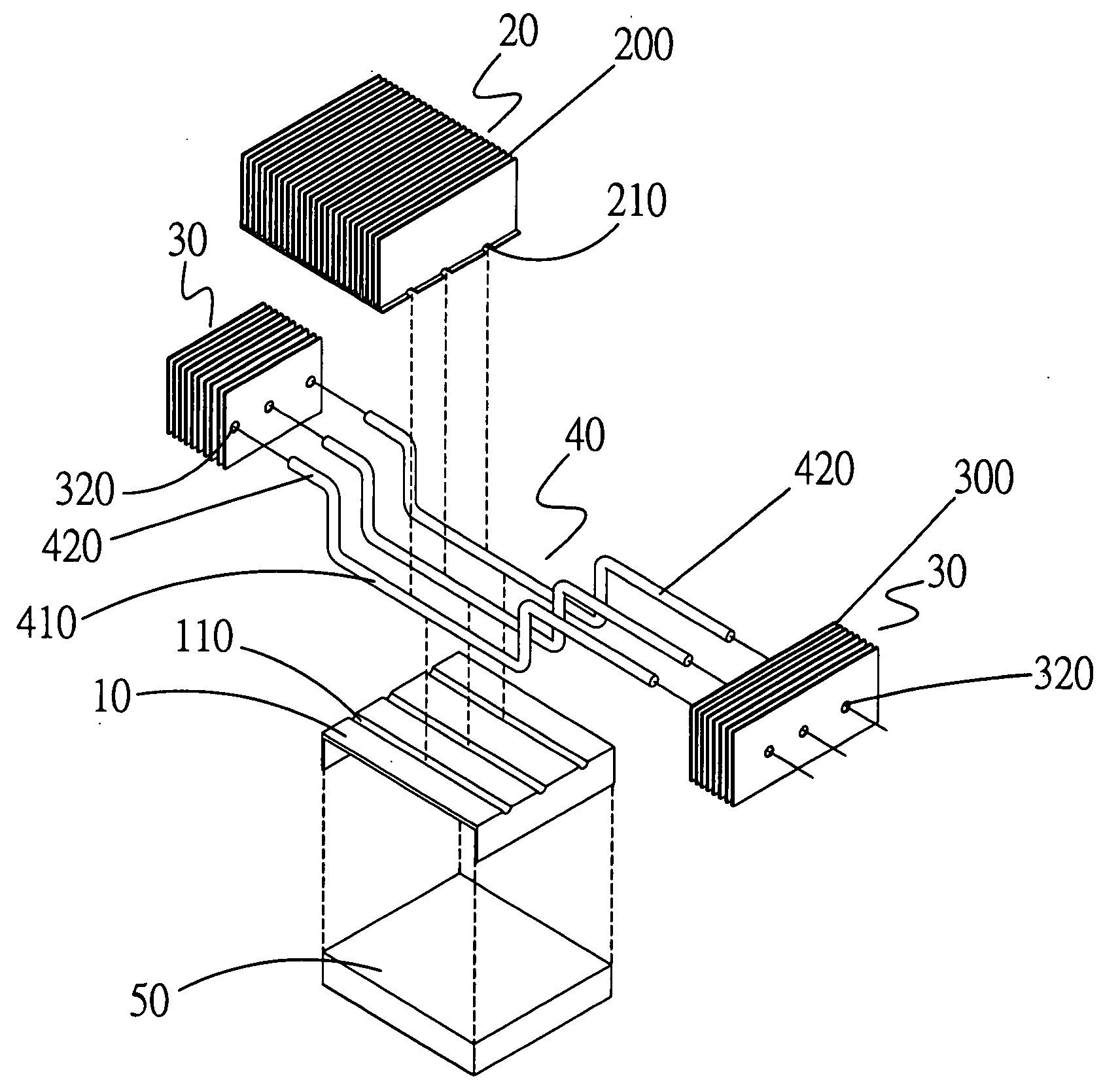
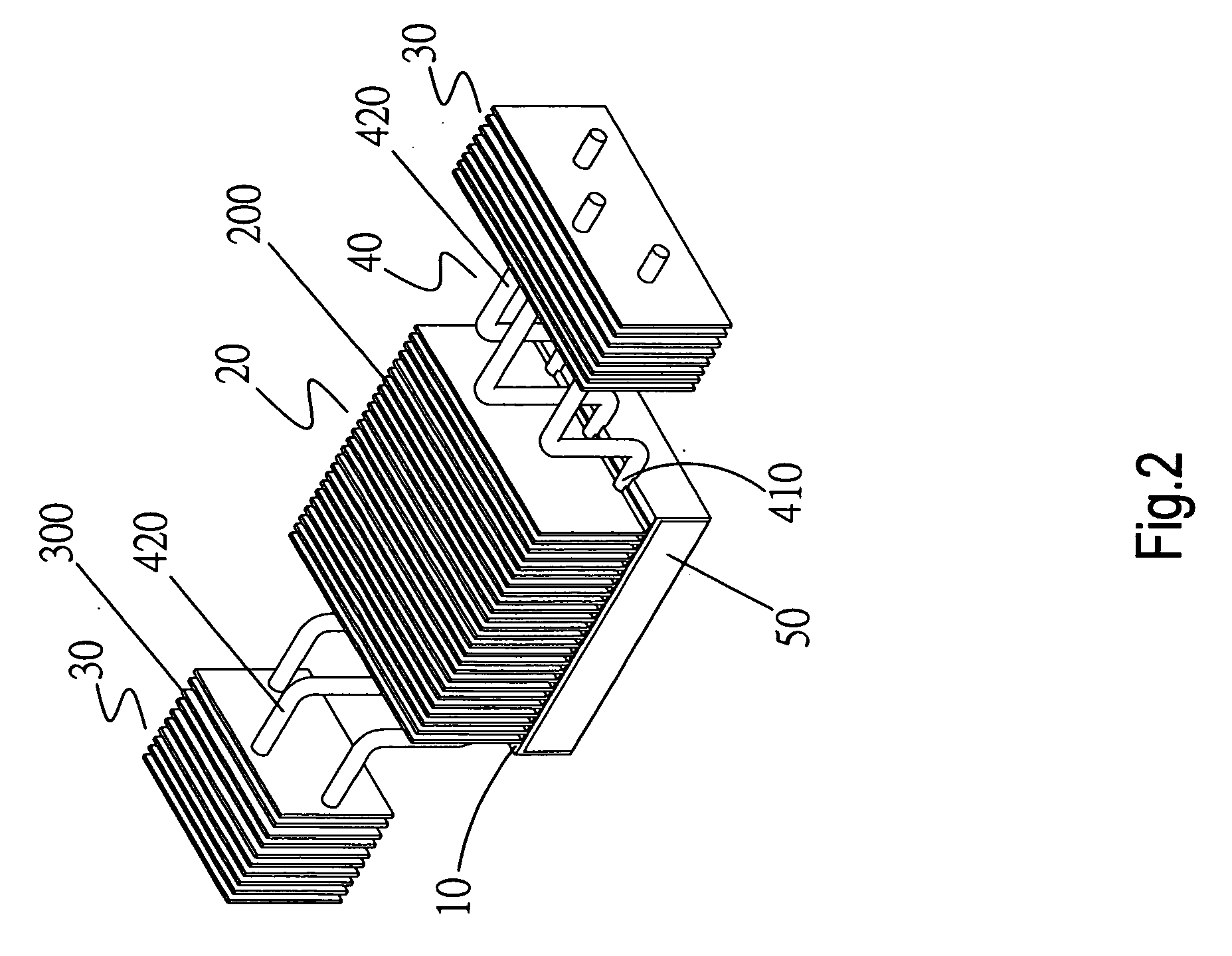
[0017]Please refer to FIGS. 2 and 3 that are assembled and exploded perspective views, respectively, of a thermal module for LED according to a preferred embodiment of the present invention, and to FIG. 4 that is an enlarged fragmentary front view of the present invention. As shown, the thermal module for LED according to the preferred embodiment of the present invention includes a base 10, a first radiating fin assembly 20, at least one second radiating fin assembly 30, and at least one heat pipe 40. An LED module 50 is in direct contact with one of two opposite sides of the base 10. In the illustrated embodiment, there are provided two second radiating fin assemblies 30. Each of the second radiating fin assemblies 30 consists of a plurality of parallelly arranged radiating fins 300 with a space d1 existing between any two adjacent radiating fins 300 to provide an air passage 310. Heat-carrying airflows (not shown) can smoothly and quickly flow through the air passages 310. With th...


PUM


Abstract

A thermal module for LED includes a base in direct contact with an LED module; a first radiating fin assembly consisting of a plurality of parallelly spaced radiating fins and being connected at one side to the base opposite to the LED module; at least one second radiating fin assembly consisting of a plurality of parallelly spaced radiating fins, so that an air passage is provided between any two adjacent radiating fins of the second radiating fin assembly; and at least one heat pipe having a conducting section extended through and closely bearing against an interface between the base and the first radiating fin assembly, and at least one radiating section outward extended from an end of the conducting section to extend through the second radiating fin assembly. The second radiating fin assembly and the air passages thereof largely upgrade the heat dissipating efficiency of the thermal module.

Description

FIELD OF THE INVENTION[0001]The present invention relates to a thermal module, and more particularly, to a thermal module for light-emitting diode.BACKGROUND OF THE INVENTION[0002]Techniques for manufacturing highly bright light-emitting diodes (LEDs) and white LED shave become matured, allowing the LEDs to be widely applied to desk lamps, projector lamps, street lamps, etc. Now, LED lamps tend to gradually replace the incandescent lamps with tungsten filament and become a major light source for indoor illumination.[0003]In the traditional incandescent lamp, a large current is supplied to flow through the tungsten filament, so that the tungsten filament is heated to glow and emit light. Unlike the conventional tungsten filament lamp, the LED is a semiconductor element. When the electrons and holes in the semiconductor material of the LED join one another to release energy, light is emitted. Therefore, only a very low current is needed to excite the LED to emit very bright light.[000...

Claims


Application Information

Patent Timeline
IPC IPC(8): F21V29/00
CPCF21V29/004F21Y2101/02F21V29/76F21V29/717F21V29/006F21Y2115/10F28D15/0275F21V29/51
Inventor QIN, TENG-ZHI
Owner ASIA VITAL COMPONENTSSHEN ZHEN
Why Eureka
Try Eureka