Air conditioning apparatus

Active Publication Date: 2011-07-14
DAIKIN IND LTD
View PDF10 Cites 12 Cited by
  • Summary
  • Abstract
  • Description
  • Claims
  • Application Information

AI Technical Summary

Benefits of technology

[0016]The advantageous effects described below can be obtained by the aspect of the present invention obtained by applying the fifth aspect of the present invention to the second aspect of the present invention. Specifically, the area below the heat source-side heat exchanger can be warmed by the juncture tube. However, the temperature of the area below the blower is prone to depend on changes in the surrounding environment, and the growth of ice can sometimes be difficult to suppress. However, in the aspect of the present invention obtained by applying the fifth aspect of the present invention to the second aspect of the present invention, the growth of ice in the area below the blower can be more reliably suppressed by sending hot gas to the area below the blower at a higher priority than to the area below the heat source-side heat exchanger, so as to give the supply of hot gas to the area below the blower priority over the supply of hot gas to the area below the heat source-side heat exchanger.
[0017]An air conditioning apparatus according to a sixth aspect of the present invention is the air conditioning apparatus according to the fifth aspect of the present invention, wherein the heat source-side heat exchanger further comprises fins. The fins are penetrated through by at least any one of the juncture tube and the first branch tube and the second branch tube, and the penetrating portion of at least any one of the first branch tube and the second branch tube, and the penetrating portion of the juncture tube are connected.
[0018]In this air conditioning apparatus, a single fin can be used in common for heat exchange of the juncture tube and heat exchange of at least a

Problems solved by technology

The surface of the outdoor heat exchanger therefore becomes covere

Method used


Image

  • Air conditioning apparatus
  • Air conditioning apparatus
  • Air conditioning apparatus

Examples


Embodiment Construction

[0088]The electromagnetic induction heating unit 6 and the air conditioning apparatus 1 provided therewith according to an embodiment of the present invention will be described below as examples with reference to the drawings.

[0089] Air Conditioning Apparatus 1

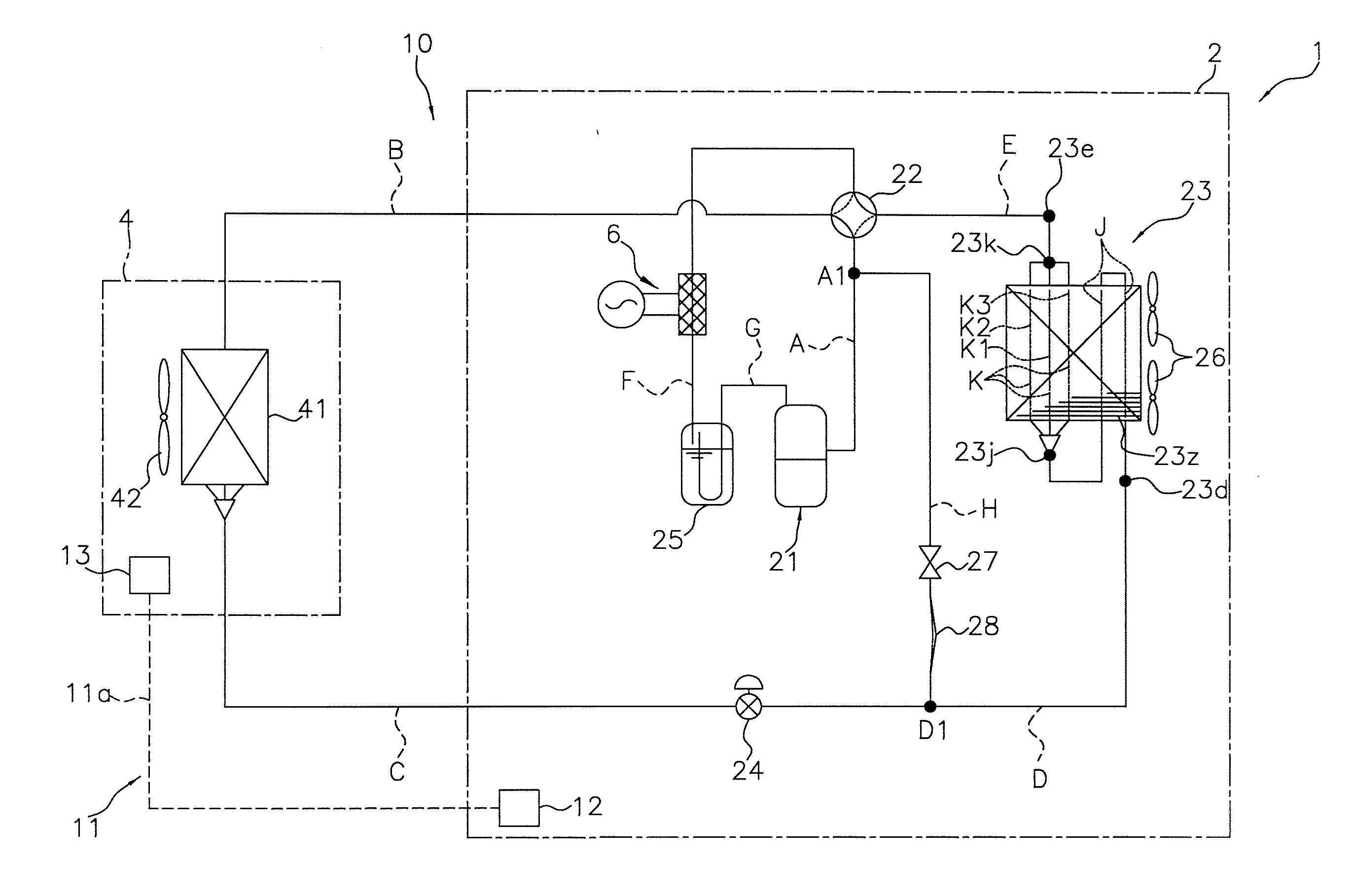
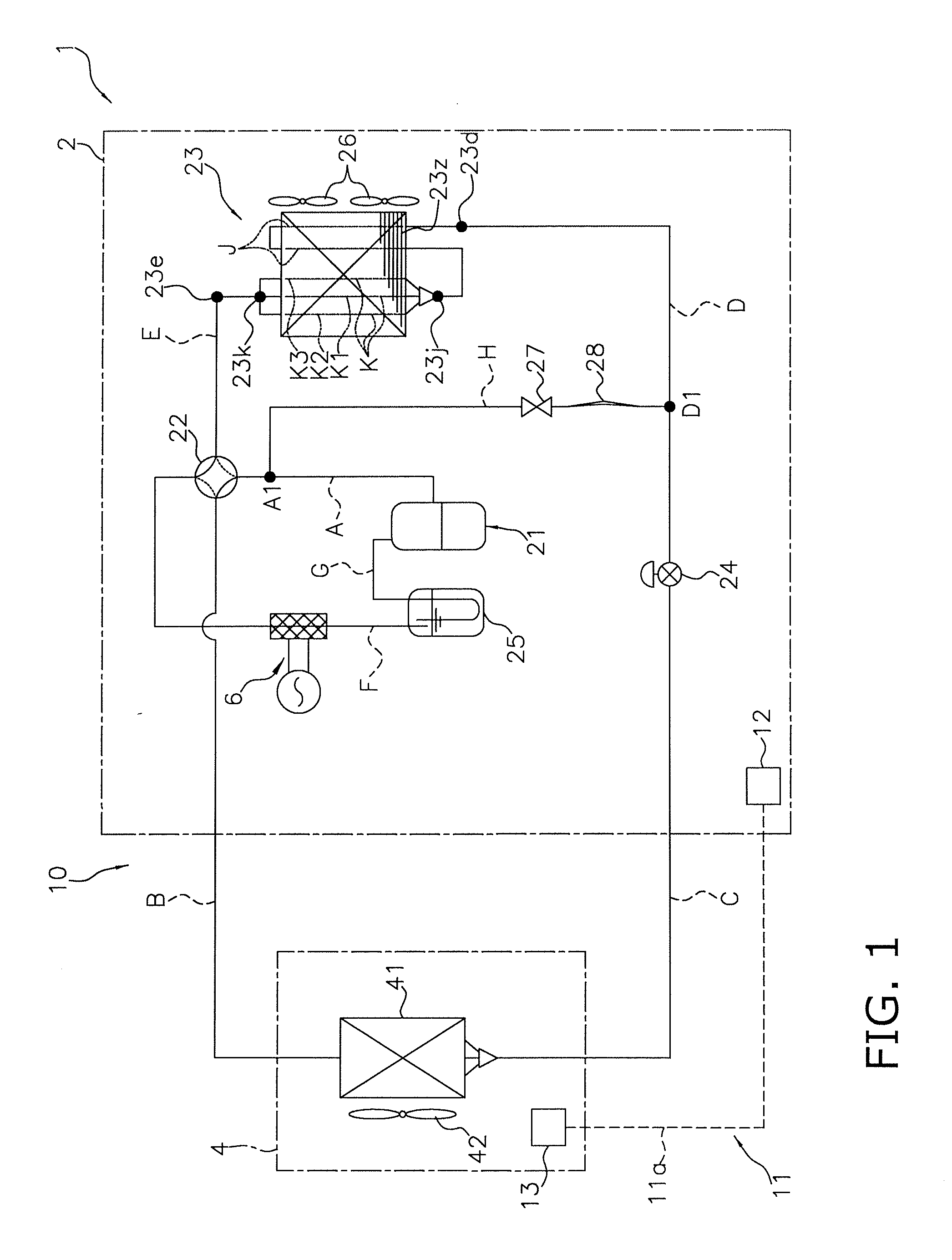
[0090]FIG. 1 is a refrigerant circuit diagram showing a refrigerant circuit 10 of the air conditioning apparatus 1.

[0091]In the air conditioning apparatus 1, an outdoor unit 2 as a heat source-side apparatus, and an indoor unit 4 as a usage-side apparatus are connected by a refrigerant tube, the air conditioning apparatus 1 performs air conditioning of a space in which a usage-side apparatus is placed, and the air conditioning apparatus 1 is provided with a compressor 21, a four-way switching valve 22, an outdoor heat exchanger 23, an outdoor motor-driven expansion valve 24, an accumulator 25, outdoor fans 26, an indoor heat exchanger 41, an indoor fan 42, a hot-gas bypass valve 27, a capillary tube 28, the electromagnetic ind...


PUM


Abstract

An air conditioning apparatus includes a compression mechanism, a heat source-side heat exchanger, an expansion mechanism, a usage-side heat exchanger, a blower, housings and a bypass circuit. The blower feeds an air flow to the heat source-side heat exchanger. The housings is configured to accommodate the heat source-side heat exchanger and the blower in a space above the bottom plate. The bypass circuit is disposed so as to pass below the blower and the heat source-side heat exchanger. The bypass circuit is configured to bypass a third refrigerant tube on a discharge side of the compression mechanism, and at least one of a first refrigerant tube and a second refrigerant tube. The first refrigerant tube extends from the usage-side heat exchanger to the expansion mechanism. The second refrigerant tube extends from the expansion mechanism to the heat source-side heat exchanger.

Description

TECHNICAL FIELD[0001]The present invention relates to an air conditioning apparatus.BACKGROUND ART[0002]During air-warming operation, a heat exchanger provided to an outdoor unit functions as a refrigerant evaporator. The outdoor air therefore condenses on the surface of the outdoor heat exchanger, and drain water is sometimes formed. Under such conditions, since the outdoor unit of the air conditioning apparatus is sometimes exposed to environments of 0° C. or lower during winter, the drain water sometimes freezes. The surface of the outdoor heat exchanger therefore becomes covered with ice, and the heat exchange performance thereof may decrease.[0003]In contrast, a technique is proposed in the air conditioning apparatus disclosed in Patent Document 1 (Japanese Unexamined Patent Application Publication No. 2008-96018) in which a heater is provided on the top surface of a bottom plate for supporting the outdoor heat exchanger of the outdoor unit, and ice is prevented from forming. W...

Claims


Application Information

Patent Timeline
IPC IPC(8): F25D21/06F25B27/00F24F1/14F24F1/30F24F5/00F25B1/00F25B39/00F25B47/02
CPCF24F1/06F24F1/14F24F1/30F25B2313/02741F25B13/00F25B47/006F25B47/022F24F2011/0089F24F11/30F24F11/42
Inventor WAKASHIMA, MASAHIROASADA, SATOSHI
Owner DAIKIN IND LTD
Why Eureka
Try Eureka