Low-profile mounted push-on connector

Inactive Publication Date: 2010-01-21
CORNING GILBERT INC
View PDF27 Cites 40 Cited by
  • Summary
  • Abstract
  • Description
  • Claims
  • Application Information

AI Technical Summary

Benefits of technology

[0008]Disclosed herein is an electrical connector that includes a shroud having a first end, a second end, and an opening extending between the first end and the second end, the opening having a first diameter in a center portion of the shroud an

Problems solved by technology

Prior coaxial connectors used on PC boards are generally too large to allow for soldering and to allow for adequate spacing on the PC board.
However, as electronics have become more compact, more compact connectors are needed.

Method used


Image

  • Low-profile mounted push-on connector
  • Low-profile mounted push-on connector
  • Low-profile mounted push-on connector

Examples


Embodiment Construction

[0024]Reference will now be made in detail to the present preferred embodiment(s) of the invention, examples of which are illustrated in the accompanying drawings. Whenever possible, the same reference numerals will be used throughout the drawings to refer to the same or like parts.

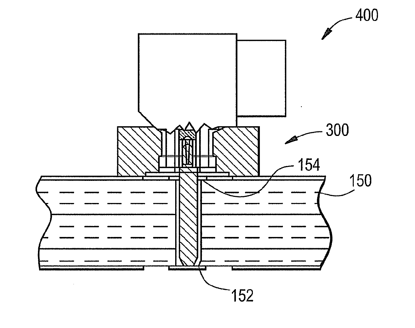
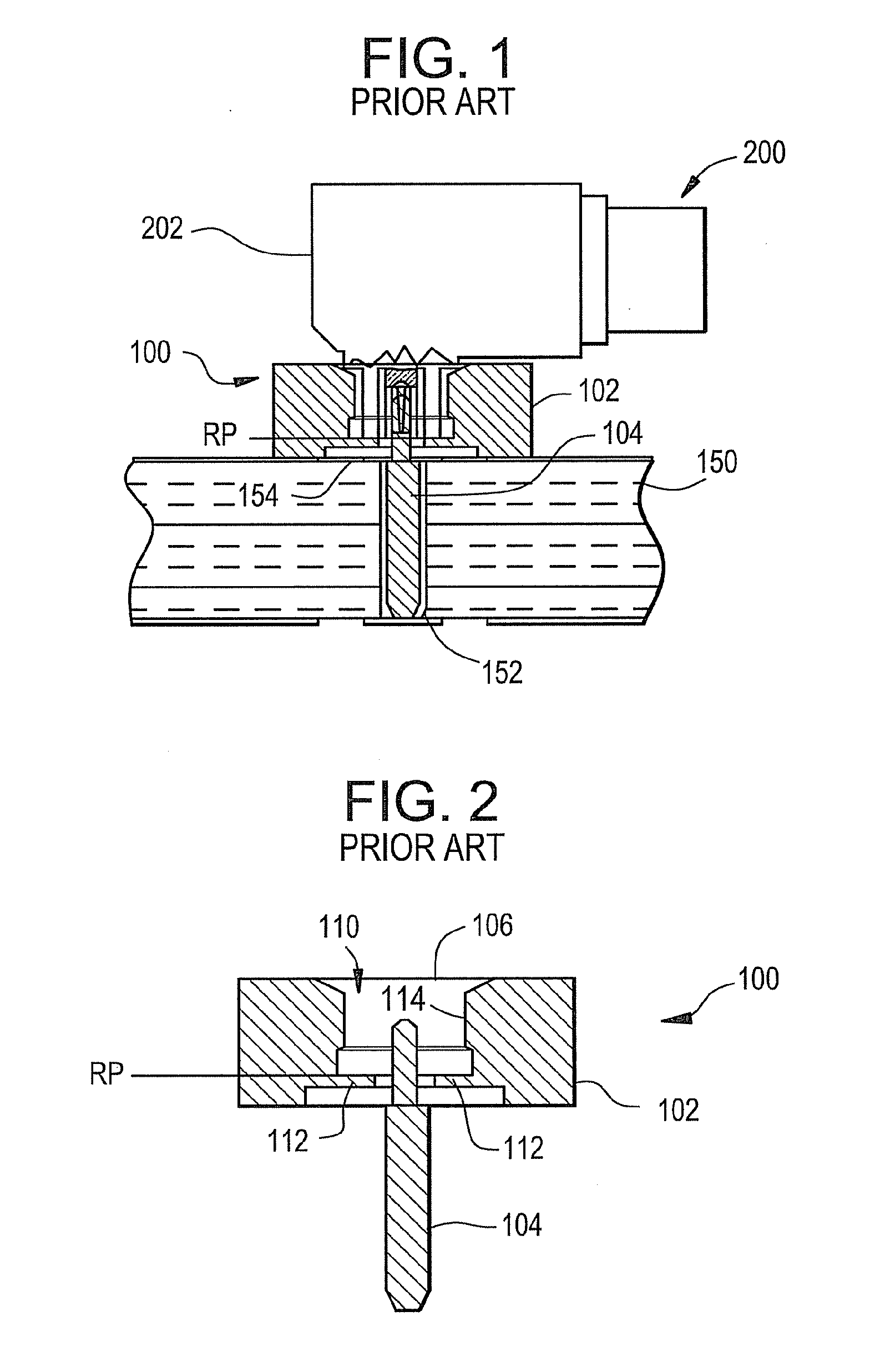
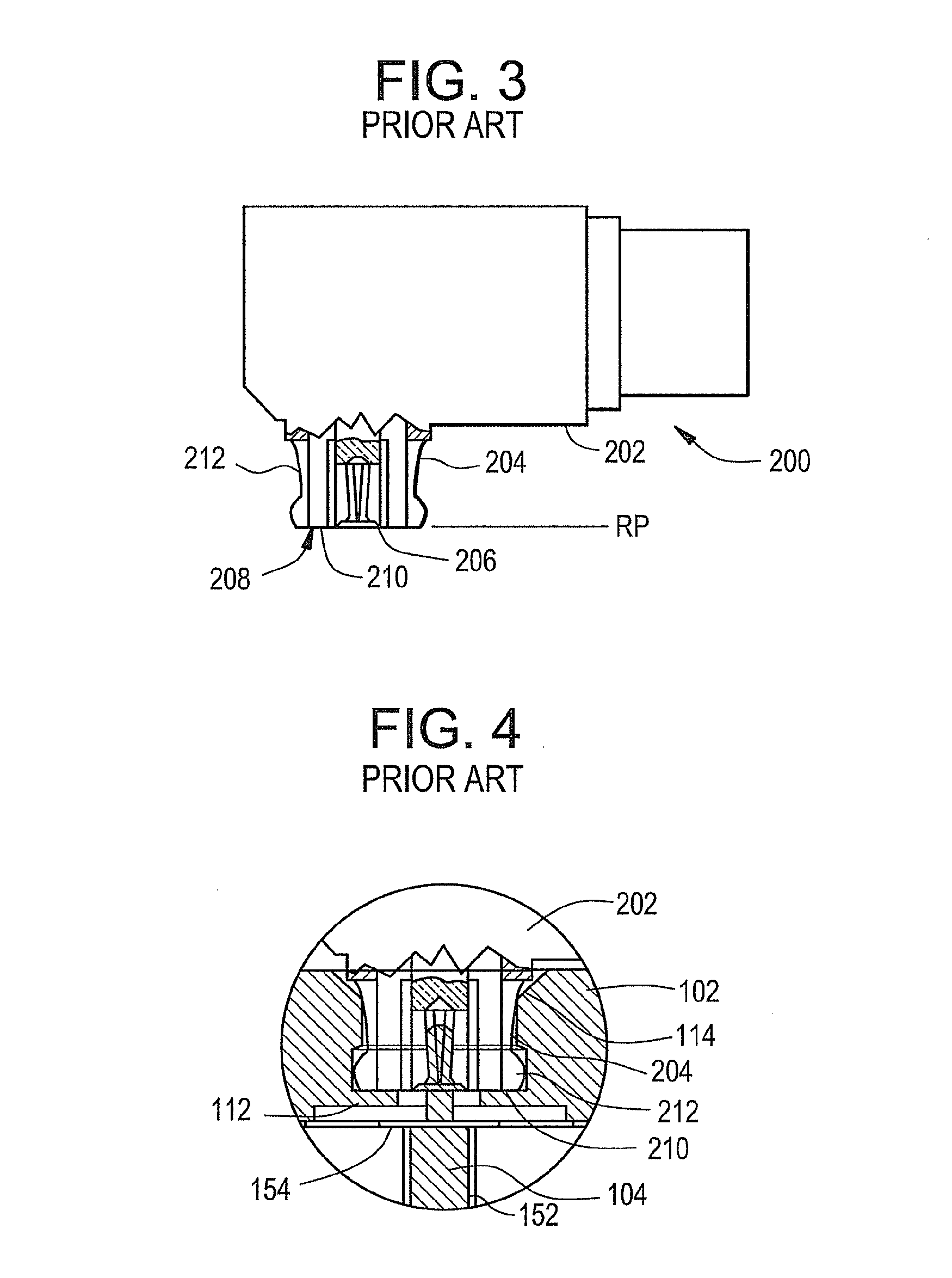
[0025]Referring to FIGS. 1-4, a prior art male electrical connector 100, mounted on a PC board 150, is illustrated as being electrically and mechanically connected to a prior art female electrical connector 200. The male electrical connector 100 illustrated in more detail in FIG. 2 includes an outer shroud 102 and a center conductor 104. The outer shroud 102 and center conductor 104 are typically independent elements, but operate as the male connector. The center conductor 104 is disposed in an opening 152 in the PC board 150 and is soldered to physically retain the center conductor 104 in the opening 152 and also to electrically connect the center conductor 104 to the solder pad 154 adjacent the opening ...


PUM


Abstract

An electrical connector has an outer shroud and a center conductor. The outer shroud has an opening with a first diameter in a center portion of the outer shroud and a second diameter adjacent a second end thereof, the first diameter being smaller than the second diameter. The outer shroud also has a first end providing a physical stop for a female connector that mates with the electrical connector. The female connector has a distal end of an outer conductor that does not engage the outer shroud of the electrical connector.

Description

CROSS-REFERENCE To RELATED APPLICATIONS[0001]This application claims the benefit of, and priority to U.S. Provisional Patent Application No. 61 / 080,784 filed on Jul. 15, 2008 entitled, “Low-Profile Mounted Push-On Connector”, the content of which is relied upon and incorporated herein by reference in its entirety.BACKGROUND OF THE INVENTION[0002]1. Field of the Invention[0003]The present invention relates generally to low-profile push-on RF connectors, and particularly to low-profile PCB-mounted push-on RF connectors that do not require standard reference planes for manufacturing.[0004]2. Technical Background[0005]Coaxial connectors used to transmit radio frequency signals for broadband telecommunications, military avionics, and microwave systems are well known in the art. Such connectors are often known as “SMP” connectors, or “SMPM” connectors, and are constructed in accordance with military standard MILSTD 348. For example, for many years, Gilbert Engineering Co., Inc. of Glendal...

Claims


Application Information

Patent Timeline
IPC IPC(8): H01R9/05
CPCH01R2103/00H01R24/50
Inventor STEIN, CASEY ROY
Owner CORNING GILBERT INC
Why Eureka
Try Eureka