In-line splice connector

a technology of in-line splicing and connectors, which is applied in the direction of contact members penetrating/cutting insulation/cable strands, electrical appliances, fastening/insulating connecting parts, etc., can solve the problems of not meeting the minimum tensile pull-out requirements, conventional in-line splice connectors are not compatible with certain categories of electrical wires, and conventional in-line splice connectors do not firmly grip wires

Inactive Publication Date: 2010-02-04
3M INNOVATIVE PROPERTIES CO
View PDF7 Cites 29 Cited by
  • Summary
  • Abstract
  • Description
  • Claims
  • Application Information

AI Technical Summary

Benefits of technology

[0011]The above summary of the present invention is not intended to describe each illustrated embodiment or every implementa...

Problems solved by technology

However, some conventional in-line splice connectors are not compatible with certain categories of electrical wire.
Also, conventiona...

Method used


Image

  • In-line splice connector
  • In-line splice connector
  • In-line splice connector

Examples


Embodiment Construction

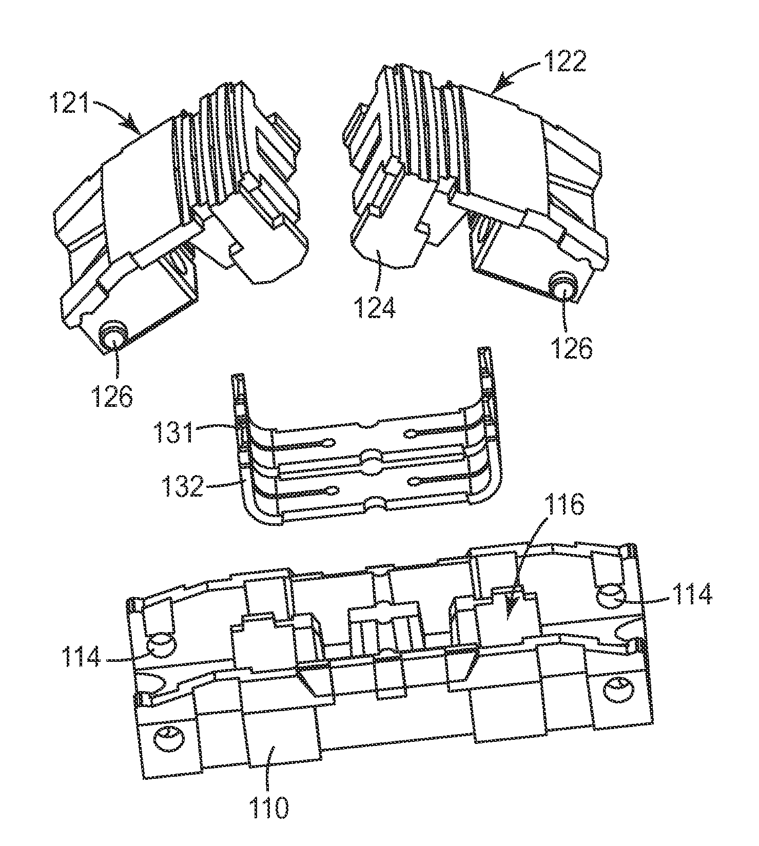
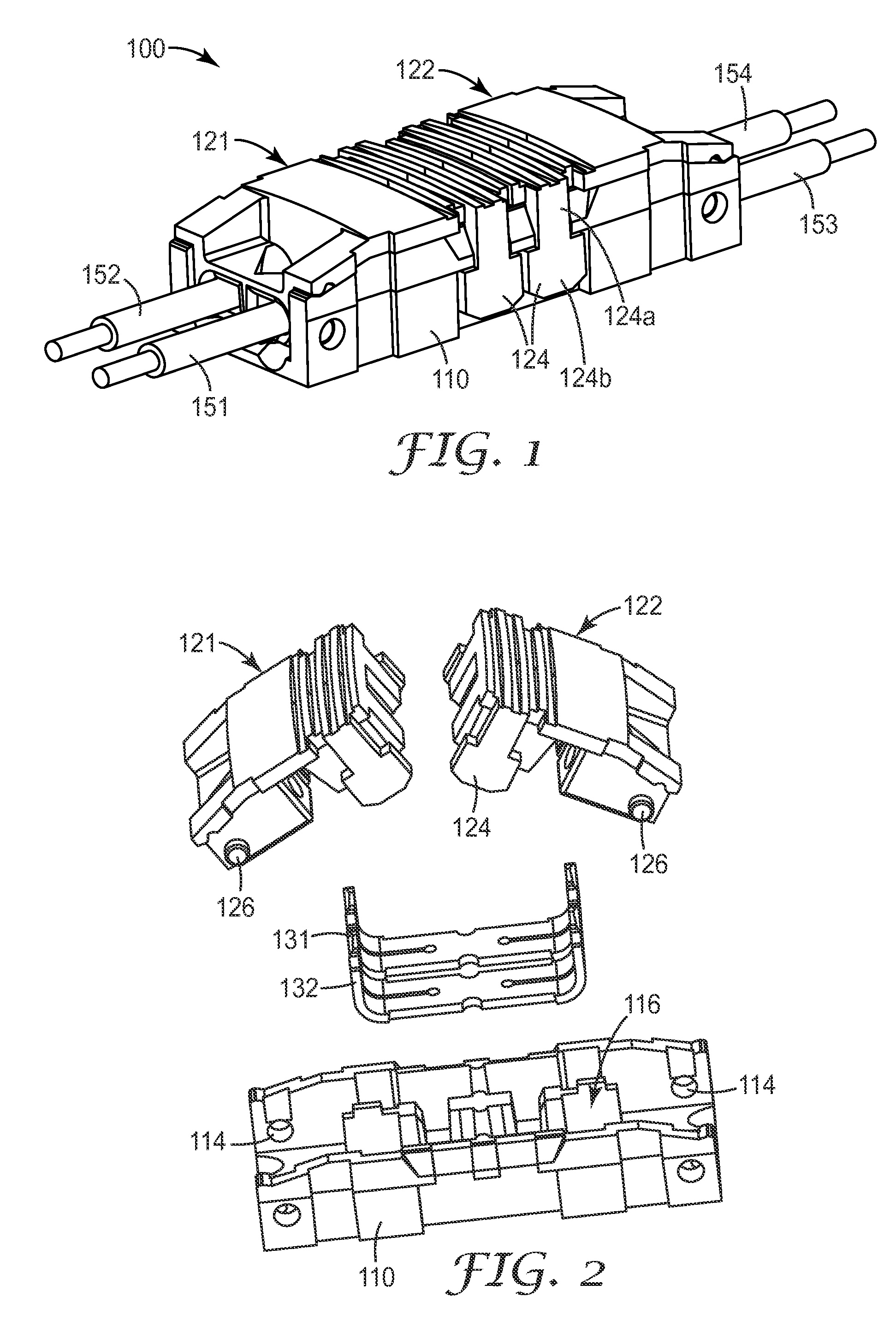
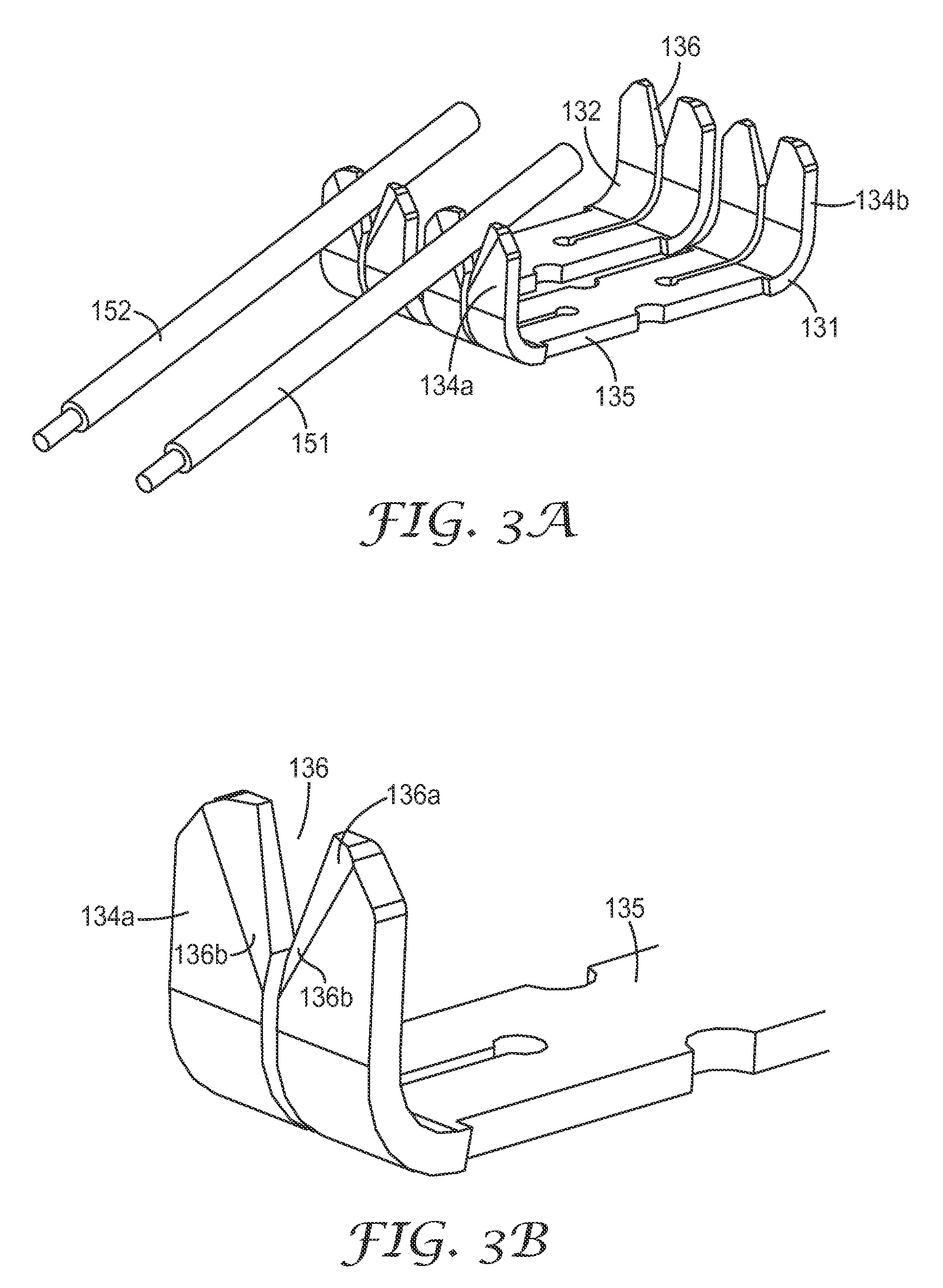
[0030]In the following Detailed Description, reference is made to the accompanying drawings, which form a part hereof, and in which is shown by way of illustration specific embodiments in which the invention may be practiced. In this regard, directional terminology, such as “top,”“bottom,”“front,”“back,”“leading,”“forward,”“trailing,” etc., may be used with reference to the orientation of the Figure(s) being described. Because components of embodiments of the present invention can be positioned in a number of different orientations, the directional terminology is used for purposes of illustration and is in no way limiting. It is to be understood that other embodiments may be utilized and structural or logical changes may be made without departing from the scope of the present invention.

[0031]The present invention is directed to an in-line splice connector for creating a splice of one or more wires of varying sizes. The in-line splice connector includes a structure and retention feat...


PUM


Abstract

An in-line splice connector comprises a connector body having a first end and a second end opposite the first end and having a generally elongated cavity region formed between the first and second ends to house at least a first insulation displacement connector (IDC) element. The in-line splice connector also includes a first cap and a second cap, each cap including a wire guide to receive and guide a wire to the IDC element. The first cap is pivotally mounted at the first end of the connector body to receive a first wire and the second cap is pivotally mounted at the second end of the connector body to receive a second wire. A closing of the first and second caps actuates a splice of the first and second wires.

Description

CROSS REFERENCE TO RELATED APPLICATION[0001]This application claims the benefit of U.S. Provisional Patent Application No. 61 / 085,922, filed Aug. 4, 2008, the disclosure of which is incorporated by reference herein in its entirety.BACKGROUND[0002]1. Field[0003]The present invention is directed to an in-line splice connector.[0004]2. Related Art[0005]An insulation displacement connector (“IDC” or “IDC element”) can be used to make the electrical connection or splice between two wires or electrical conductors. The IDC element displaces the insulation from a portion of the electrical conductor when the electrical conductor is inserted into a slot within the IDC element such that the IDC element makes an electrical connection to the electrical conductor. Once the electrical conductor is inserted into the slot, and the wire insulation is displaced, electrical contact is made between the conductive surface of the IDC element and the conductive core of the electrical conductors that contac...

Claims


Application Information

Patent Timeline
IPC IPC(8): H01R4/24
CPCH01R4/2433
Inventor COX, LARRYBERGLUND, SIDNEY J.PRATT, JEROME A.
Owner 3M INNOVATIVE PROPERTIES CO
Why Eureka
Try Eureka