Vehicle latch with secondary engagement between cam and auxiliary pawl

Active Publication Date: 2010-03-04
MAGNA CLOSURES SPA
View PDF9 Cites 29 Cited by
  • Summary
  • Abstract
  • Description
  • Claims
  • Application Information

AI Technical Summary

Problems solved by technology

In such a situation, the vehicle latch can move to a release position, there

Method used


Image

  • Vehicle latch with secondary engagement between cam and auxiliary pawl
  • Vehicle latch with secondary engagement between cam and auxiliary pawl
  • Vehicle latch with secondary engagement between cam and auxiliary pawl

Examples


Embodiment Construction

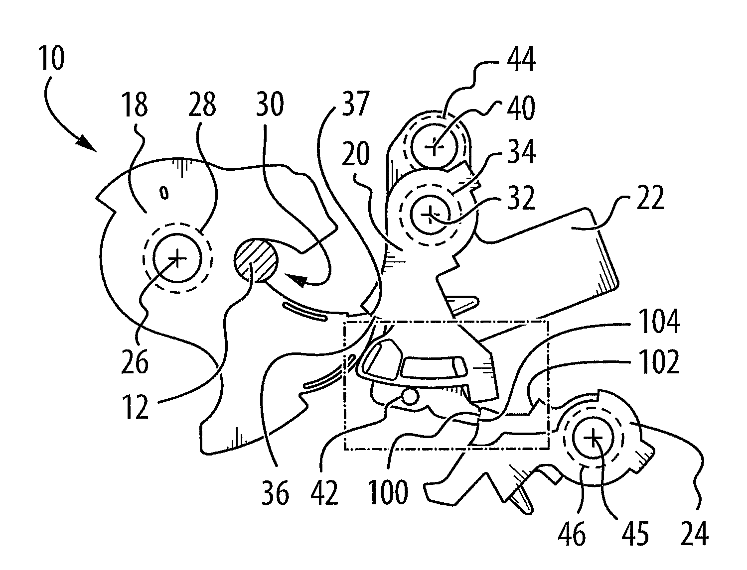
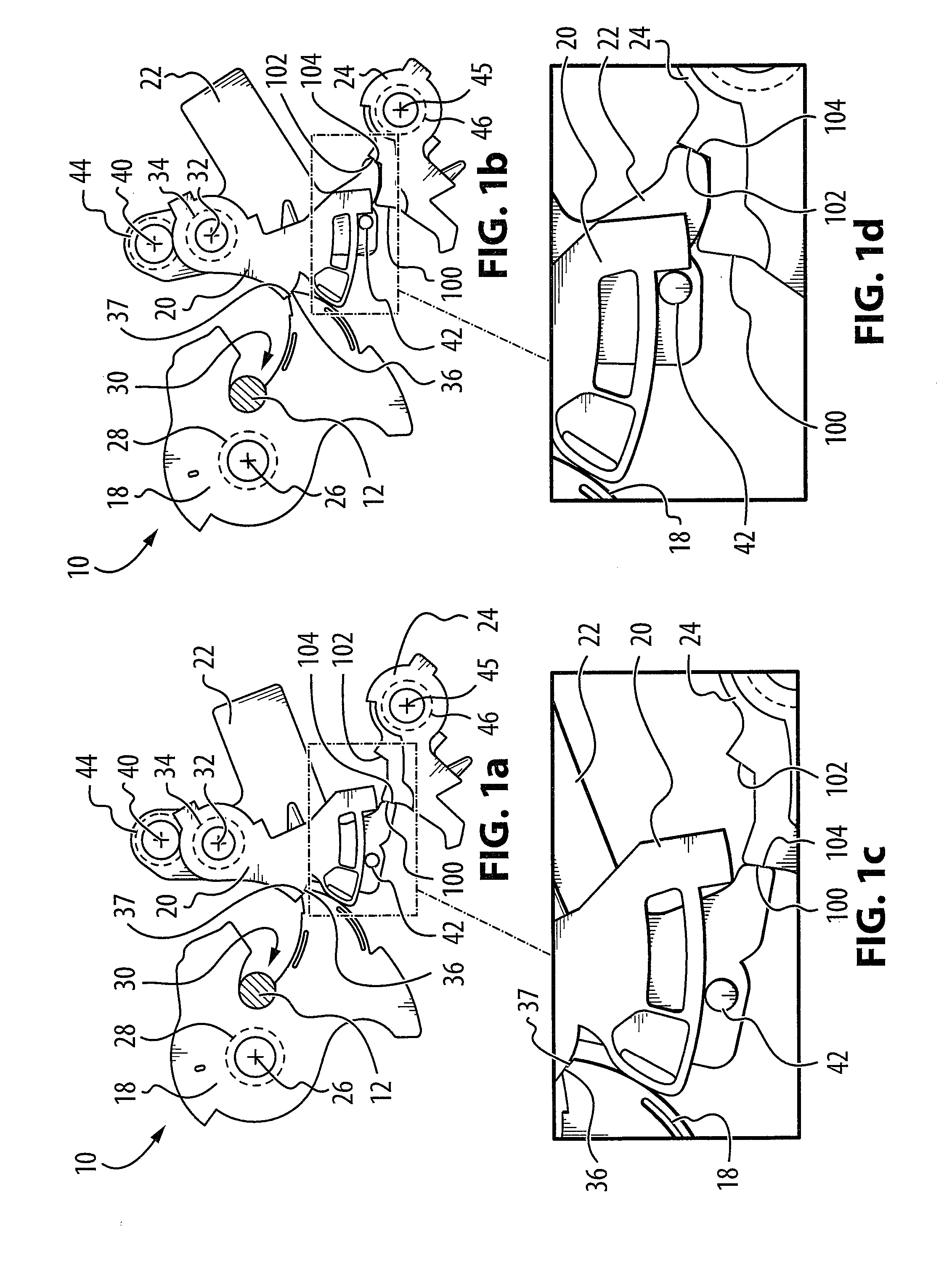
[0029]Reference is made to FIG. 1a, which shows a vehicle latch 10 for receiving and holding a striker 12. The vehicle latch 10 may be mounted on a vehicle door (not shown), while the striker 12 may be mounted on a vehicle body (not shown).

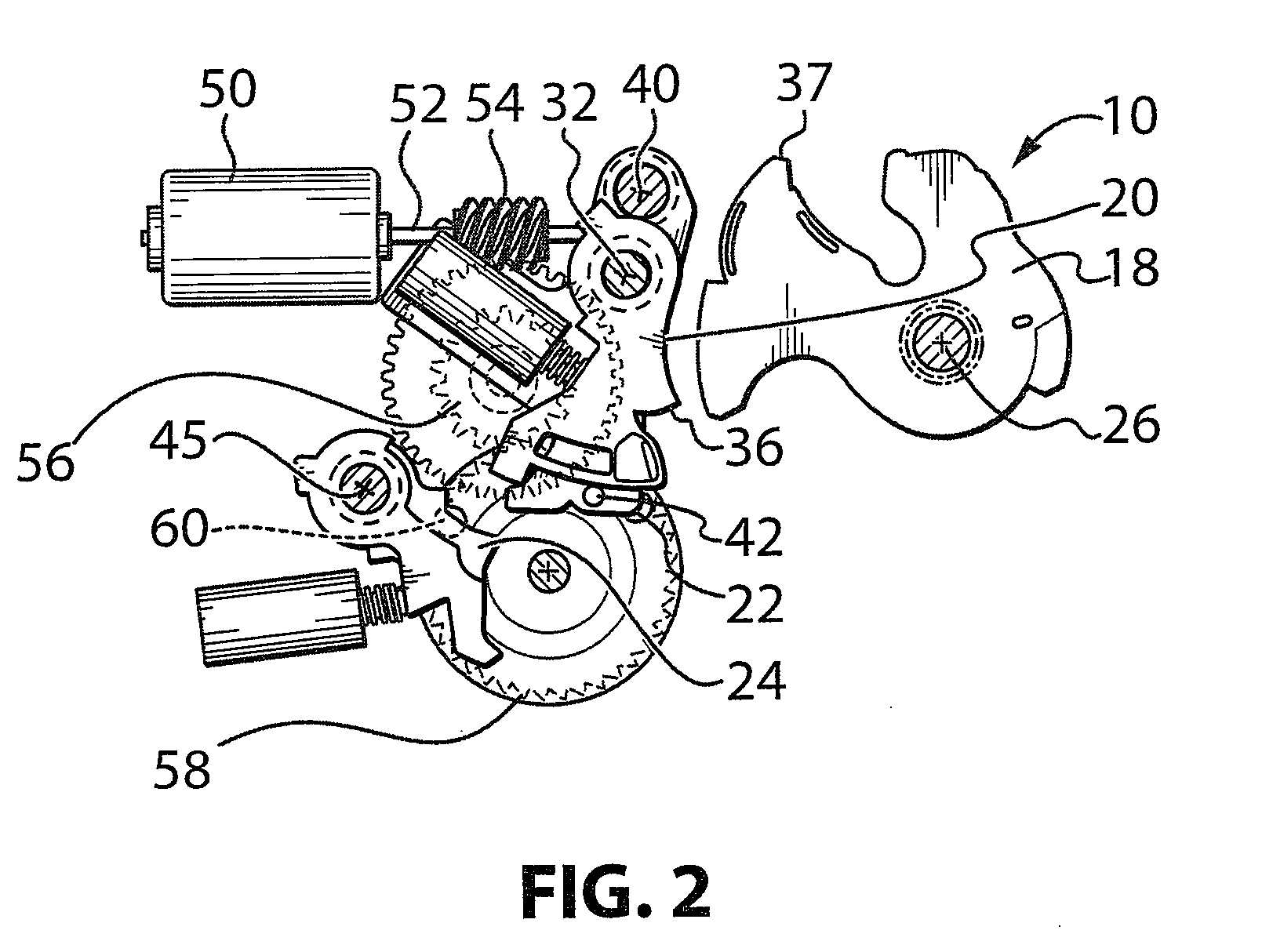
[0030]The latch 10 includes a ratchet 18, a main pawl 20, a cam 22 and an auxiliary pawl 24. The ratchet 18 is pivotally mounted to a latch housing (not shown) the vehicle door for pivotal movement about a ratchet pivot axis shown at 26. The ratchet 18 is movable between a ratchet open position (not shown) wherein the ratchet 18 is positioned to receive the striker 12, and a ratchet locking position (FIG. 1a) wherein the ratchet 18 is positioned to retain the striker 12. The ratchet 18 is biased towards the ratchet open position by a ratchet biasing element 28, which may be, for example, a torsion spring.

[0031]The ratchet 18 includes a slot 30 that is configured to hold the striker 12 when the ratchet 18 is in the ratchet locking position, thereby...


PUM


Abstract

In a first aspect, the invention is directed to a vehicle latch including a ratchet, a main pawl, a cam, and at least one auxiliary pawl, wherein a secondary engagement is provided between the cam and the at least one auxiliary pawl in case a primary engagement between the cam and at least one auxiliary pawl is missed. In a particular embodiment of the first aspect, the ratchet is movable between a ratchet open position wherein the ratchet is positioned to receive a striker and a ratchet locking position wherein the ratchet is positioned to retain the striker. The ratchet is biased towards the ratchet open position. The main pawl is movable between a main pawl locking position wherein the main pawl is positioned to hold the ratchet in the ratchet locking position and a main pawl release position wherein the main pawl permits the movement of the ratchet out of the ratchet locking position. The main pawl is biased towards the main pawl locking position. The cam is operatively connected to the main pawl. The cam is movable between at least two main pawl enabling positions in which the main pawl is enabled to move to the main pawl locking position, and a main pawl disabling position in which the cam positions the main pawl in the main pawl release position. The cam is biased towards the main pawl disabling position. The at least one auxiliary pawl is movable to hold the cam in each of the at least two main pawl enabling positions and movable to permit the cam to move to the main pawl disabling position.

Description

[0001]This application claims the benefits of U.S. Provisional Application No. 61 / 094,074, filed Sep. 4, 2008.FIELD OF THE INVENTION[0002]The present invention relates to a closure latch for a vehicle closure panel, and more particularly to safety systems for a closure latch with a ratchet, a main pawl, a cam and an auxiliary pawl.BACKGROUND OF THE INVENTION[0003]Some vehicle door latches include a ratchet, a main pawl, a for controlling the position of the main pawl, and an auxiliary pawl for controlling the position of the cam. In such a latch, if a mistiming occurs between the cam and the auxiliary pawl, the cam may sweep past its intended position prior to the auxiliary pawl reaching the intended position such that they do not engage each other. In such a situation, the vehicle latch can move to a release position, thereby inadvertently releasing the striker and thereby opening the vehicle door. It is desirable to inhibit this situation from occurring.SUMMARY OF THE INVENTION[00...

Claims


Application Information

Patent Timeline
IPC IPC(8): E05C19/00
CPCE05B85/26E05B81/14Y10T292/1047Y10T292/1082Y10T292/444
Inventor TAURASI, MARCOTAVIANI, CORRADO
Owner MAGNA CLOSURES SPA
Why Eureka
Try Eureka