
Seat structure

a seat and seat technology, applied in the field of seat structures, can solve the problems of significant limited leg room (footrest) space of passengers in the rear seat, and deterioration in comfor

Inactive Publication Date: 2010-04-29
DELTA TOOLING CO LTD
View PDF16 Cites 5 Cited by
  • Summary
  • Abstract
  • Description
  • Claims
  • Application Information

AI Technical Summary

Benefits of technology

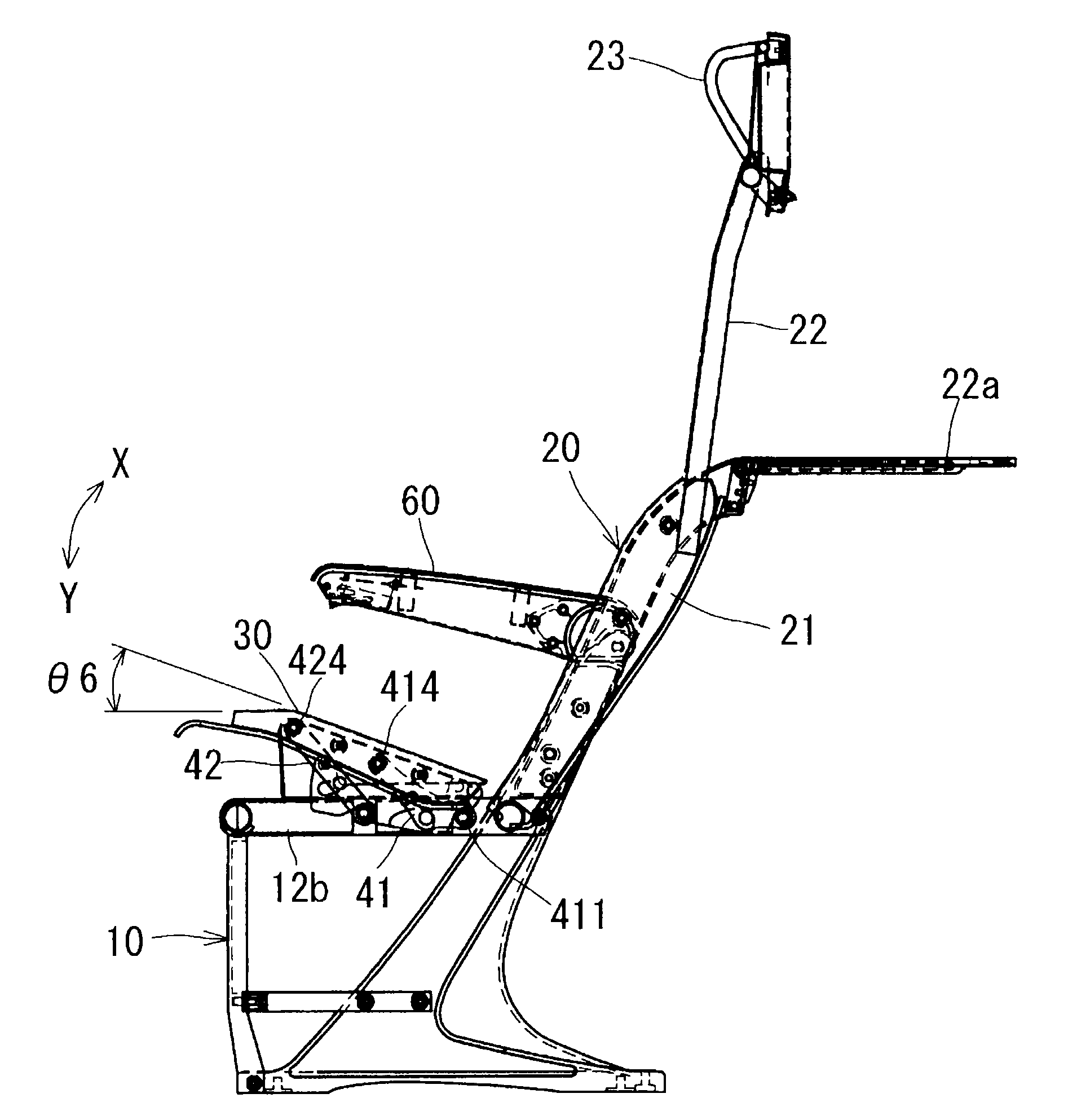
[0009]According to a seat structure of the present invention, a cushion frame is supported by a rear link plate and a front link plate, in which it is set such that the rear link plate within its movable range has a displacement angle larger than a displacement angle of the front link plate, and an angle between a side frame portion of a base frame and the rear link plate becomes smaller than an angle between the side frame portion and the front link plate when the plates are rotated and moved to the forward-most positions. Consequently, a seating surface angle of the cushion frame increases as the rear link plate and the front link plate are rotated and moved forward. In other words, according to the present invention, it is structured such that an inclination angle of a back frame itself does not vary but the seating surface angle of the cushion frame can be varied according to a movement of a person. Therefore, a person's pelvis portion and a portion lower than the pelvis portion can be moved forward without varying a position of a part of his or her back above his or her breast. Accordingly, the same effect of the resting posture, that is, the posture in which the back frame is reclined in a conventional seat structure, can be obtained. Meanwhile, since the position of the back frame supported by the base frame is not varied, a leg room space in a rear seat is not limited even when a resting posture is taken in a front seat within a same space as conventional.

Problems solved by technology

In particular, there has been a problem that, when a passenger in a front seat reclines a seat back to take a resting posture, the leg room (footrest) space of a passenger in a rear seat is significantly limited and this causes deterioration in comfort.

Method used


Image

  • Seat structure
  • Seat structure
  • Seat structure

Examples


Embodiment Construction

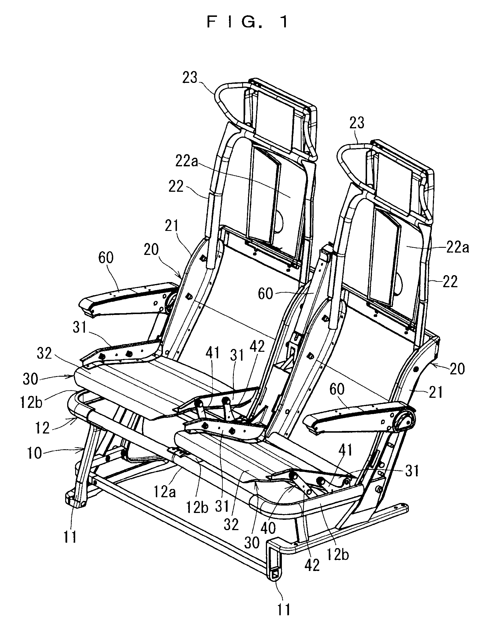
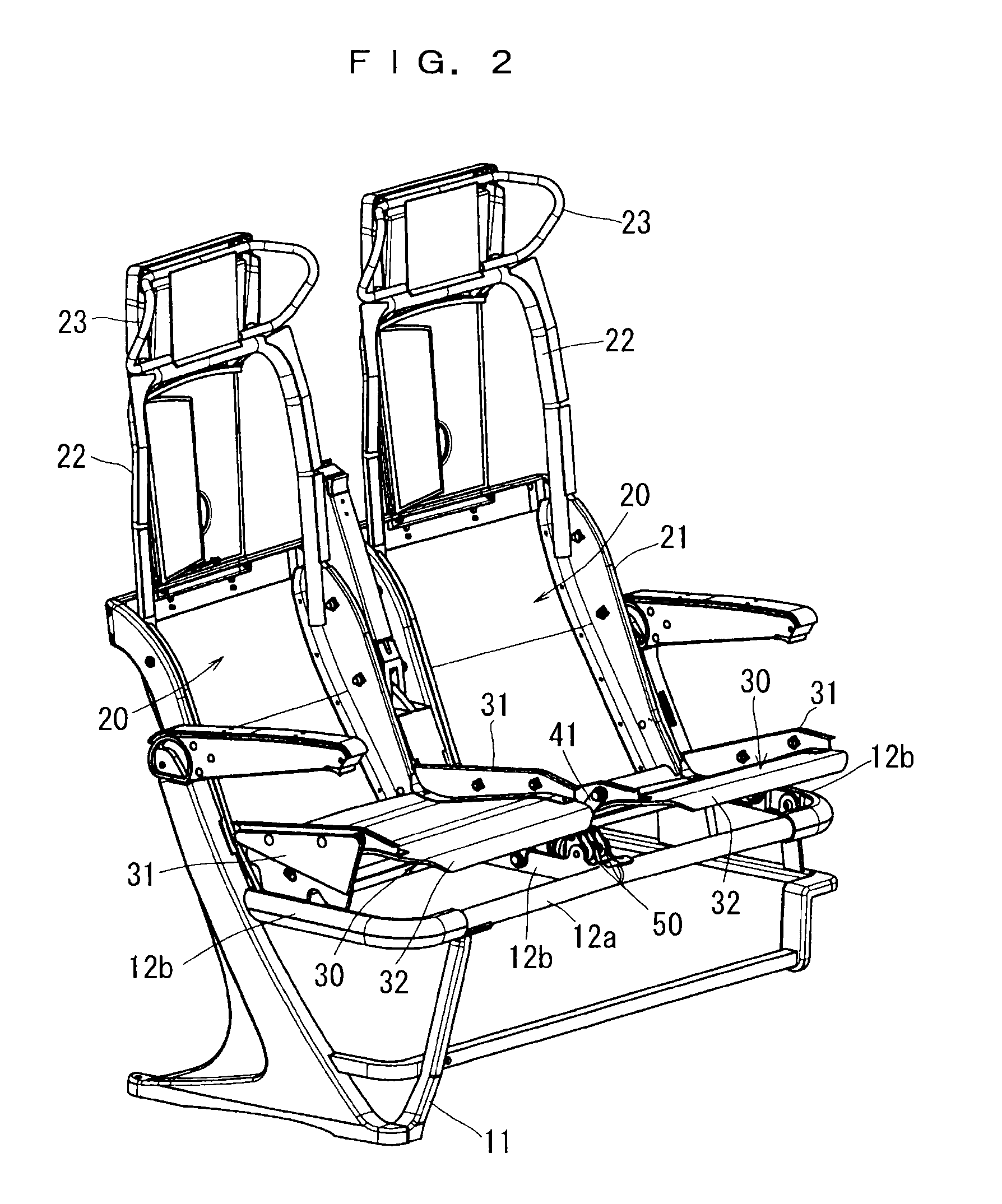
[0034]Hereinafter, the present invention will be further specifically described based on an embodiment shown in the drawings. FIG. 1 to FIG. 5 show one embodiment of the present invention. The present embodiment shows a two-seater seat structure in which two sets of back frames 20 and cushion frames 30 are supported by one set of base frame 10.

[0035]The base frame 10 is provided on a vehicle body floor of a vehicle (not shown), a floor of a theater such as a movie theater (not shown) or the like. In the present embodiment, the base frame 10 has a leg part 11 fixed to the vehicle body floor or the like, and a support frame 12 provided at a predetermined height from a floor by the leg part 11. The support frame 12 is formed in a substantially U shape, and a front frame 12a between side frame portions 12b at both ends of the support frame 12 has a length along which the two sets of cushion frames 30 can be supported in parallel. Further, on an intermediate portion of the front frame 12...


PUM


Abstract

A seat structure applicable to both a normal posture and a comfortable posture, in which a sufficiently relaxed resting posture is available and an excellent comfort is obtained while seated. A cushion frame is supported by a rear link plate and a front link plate, set such that the rear link plate within its movable range has a displacement angle larger than a displacement angle of the front link plate, and an angle between a side frame portion of a base frame and the rear link plate becomes smaller than an angle between the side frame portion and the front link plate when the plates are rotated and moved to the forward-most positions. Consequently, a seating surface angle of the cushion frame increases as the rear link plate and the front link plate are rotated and moved forward. An inclination angle of a back frame itself does not vary but the seating surface angle of the cushion frame can be varied according to a movement of a person.

Description

TECHNICAL FIELD[0001]The present invention relates to a seat structure applicable to transportation devices such as aircrafts, trains, ships, forklifts and vehicles, or various theaters such as movie theaters in which the seats are provided, and particularly relates to a seat structure of aircrafts, trains, and various theaters in which plural seats are aligned in a longitudinal direction to provide a seating space (leg room space) which is wider than a conventional seating space.BACKGROUND ART[0002]In an aircraft, for example, a number of seats are continuously provided in a longitudinal direction to arrange a predetermined number of seats in a limited space. The seating space of each passenger is thus limited to be a predetermined size. In particular, there has been a problem that, when a passenger in a front seat reclines a seat back to take a resting posture, the leg room (footrest) space of a passenger in a rear seat is significantly limited and this causes deterioration in com...

Claims


Application Information

Patent Timeline
IPC IPC(8): A47C1/022B60N2/02B64D11/06A47C1/12
CPCB60N2/1695B60N2/1814B60N2/1846B64D11/064B60N3/004B64D11/06B60N2/1853B64D11/0638
Inventor SAKAMOTO, YUTAKA
Owner DELTA TOOLING CO LTD
Learn More