Spark plug manufacturing method, and spark plug

US20100109502A1Inactive Publication Date: 2010-05-06NGK SPARK PLUG CO LTD

Image

  • Spark plug manufacturing method, and spark plug
  • Spark plug manufacturing method, and spark plug
  • Spark plug manufacturing method, and spark plug

Examples


Embodiment Construction

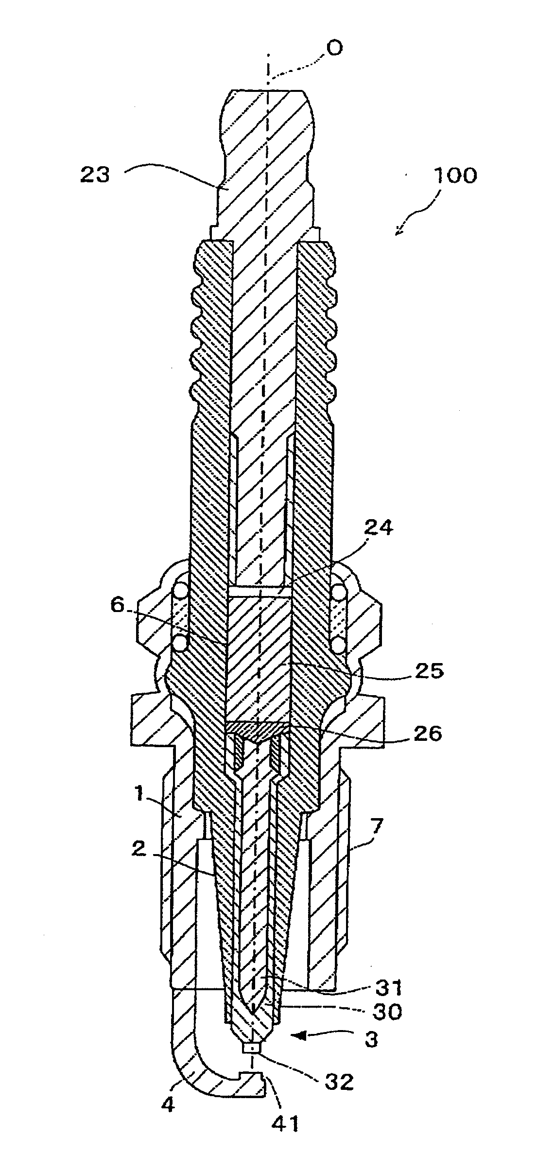
[0024]The present invention will be described in detail below with reference to the drawings. Herein, like parts and portions are designated by like reference numerals to avoid repeated explanations thereof.

[0025]As shown in FIG. 1, a spark plug 100 according to one embodiment of the present invention includes a metal shell 1, a ceramic insulator 2, a center electrode 3 and a ground electrode 4.

[0026]The metal shell 1 is made of metal such as low carbon steel and formed into a cylindrical shape. A threaded portion 7 is formed on an outer circumferential surface of the metal shell 11 and adapted for mounting the spark plug 100 onto an engine block (not shown).

[0027]The ceramic insulator 2 is made of sintered ceramic such as alumina or aluminum nitride and retained in the metal shell 11 with a front end portion of the ceramic insulator 2 protruding from an end face of the metal shell 1.

[0028]A through hole 6 is formed through the ceramic insulator 2 in the direction of an axis O. The ...


PUM


Abstract

There is provided according to the present invention a manufacturing method of a spark plug that includes a cylindrical metal shell, a cylindrical ceramic insulator retained in the metal shell, a center electrode retained in the ceramic insulator and extending in an axial direction and a ground electrode having a rear end portion fixed to the metal shell and a front end portion formed with a protruding region facing a front end portion of the center electrode with a gap left therebetween and being of substantially uniform thickness except for an area where the protrusion is formed. The spark plug manufacturing method includes a press forming step for pressing the whole of a ground electrode material for constituting the ground electrode, so as to form a protruding region on a front end portion of the ground electrode material and a welding step for, after the press forming step, welding a rear end portion of the ground electrode material to the metal shell.

Description

TECHNICAL FIELD[0001]The present invention relates to a method of manufacturing a spark plug for use in an automotive internal combustion engine etc. and a spark plug.BACKGROUND ART[0002]A spark plug is known which include a center electrode and a ground electrode arranged at a discharge gap away from a front end portion of the center electrode so as to generate a spark discharge between the center electrode and the ground electrode for ignition of an air-fuel mixture in a combustion chamber of an internal combustion engine.[0003]Amid recent calls for global environmental protection, it is more strongly demanded to provide energy savings, regulate emissions of carbon dioxide and reduce emissions of unburned gases (hydrocarbon compounds). In order to satisfy these demands, developments are being actively made in internal combustion engines such as lean-burn engine, direct gasoline-injection engine and low emission gas engine. Further, exhaust gas recirculation (EGR) systems, which re...

Claims


Application Information

Patent Timeline
06 May 2010
Publication
US20100109502A1
IPC
H01T13/20; H01T21/02
CPC
H01T13/32; H01T21/02
Inventors
NAKAYAMA, KATSUTOSHI; NAGASAWA, SATOSHI