Ir camera with adjustable view parameter settings

a technology of view parameter and adjustable setting, which is applied in the field of ir cameras, can solve the problems of difficult to adjust the settings of view parameters for an inexperienced user, difficult to understand and use manual inputs, and difficult to interpret what you actually do, so as to achieve easy and simple adjustment of view parameter settings

Active Publication Date: 2010-05-27
FLIR SYST AB
View PDF4 Cites 41 Cited by
  • Summary
  • Abstract
  • Description
  • Claims
  • Application Information

AI Technical Summary

Benefits of technology

[0008]A problem to which the invention relates is how to provide an easy and simp

Problems solved by technology

For an inexperienced user, the manual inputs may be difficult to understand and inefficient to use.
Furthermore, it may also be difficult for an inexperienced user to know how to adjust the settings of the view parameters in order to see other objects, particularly, if the IR camera is in a fusion mode where the temperatures that are bottomed (flattened) are replaced with a visual image, that is, the pixels having a temperature that are outside the thermal image colours span being replaced with visual image pixels

Method used


Image

  • Ir camera with adjustable view parameter settings
  • Ir camera with adjustable view parameter settings
  • Ir camera with adjustable view parameter settings

Examples


Embodiment Construction

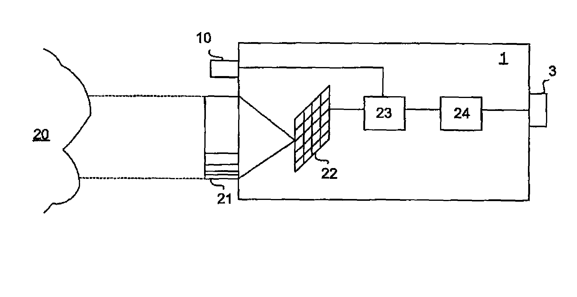
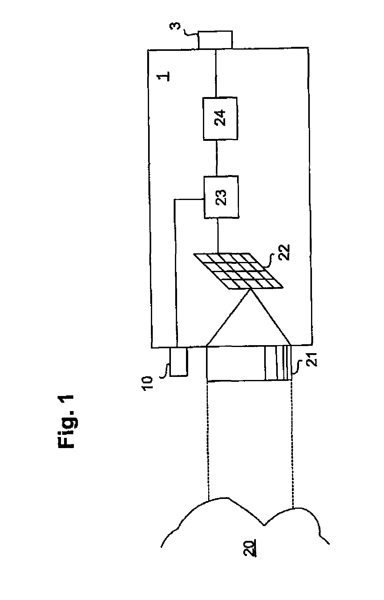
[0030]FIG. 1 shows an IR camera 1 according to an embodiment of the invention arranged to automatically adjust the view parameter settings of an IR camera display 3. The IR camera 1 may comprise at least one lens arrangement 21, a detector array 22, a signal conditioning and processing unit 23 and a display control unit 24. The IR camera 1 may also comprise a pointing light source 10.

[0031]The incoming radiation to the IR camera 1 is focused by at least one lens arrangement 21 onto the detector array 22. The detector array 22 may typically be a matrix of detector elements, each of which may detect radiation from a corresponding area on an object 20, for example, a wall, water pipes, electrical connectors, etc., that is being imaged. The detector array 22 may, for example, be a focal plane array (FPA).

[0032]From the detector array 22, the thermal image signal comprising temperature measurement data may be fed to a signal conditioning and processing unit 23. The signal conditioning an...


PUM


Abstract

The invention relates to an IR camera for capturing thermal images of an imaged view, the IR camera comprising an IR camera display arranged to display the captured thermal images to a user of the IR camera according to a view parameter setting. The IR camera is characterized in that it further comprises a display control unit arranged to automatically adjust the view parameter setting in the IR camera display based on a temperature reference area in the captured thermal images, wherein the temperature reference area is obtained using an indication means when a manual indication is performed by the user of the IR camera. The invention further relates to a method for adjusting view parameter settings in an IR camera and a computer program product.

Description

FIELD OF THE INVENTION[0001]The invention relates in general to an IR camera, and in particular to an IR camera comprising an IR camera display with adjustable view parameter settings. The invention also relates to a method for adjusting view parameter settings in an IR camera and a computer programme product for the same.BACKGROUND OF THE INVENTION[0002]Infrared (IR) thermal cameras can be used in a number of different situations, for example, when inspecting or surveying complex electrical systems such as transformers, switchgears, etc., or water carrying systems such as heat exchangers, radiators, etc. IR cameras are used for capturing, displaying and storing thermal images. The thermal images may then be viewed and analyzed in order to, for example, find faulty electrical wirings or couplings, leaking water pipes, etc.[0003]When viewing a thermal image captured by an IR camera in an IR camera display, there are a number of different view parameters that determines how the therma...

Claims


Application Information

Patent Timeline
IPC IPC(8): H01L31/00
CPCG02B23/12H04N5/332H04N5/33H04N5/23293H04N23/633H04N23/11
Inventor JONSSON, HENRIKGEORGE-SVAHN, ERLAND
Owner FLIR SYST AB
Why Eureka
Try Eureka